Dental Syringe

a dental syringe and carpule technology, applied in the field of dental syringe and carpule, can solve the problems of the harpoon not disengaged from the piston or plug, and achieve the effect of avoiding the inadvertent withdrawal of the piston

Active Publication Date: 2018-01-25
JEAN CHARLES GERMAIN +1
View PDF14 Cites 2 Cited by
  • Summary
  • Abstract
  • Description
  • Claims
  • Application Information

AI Technical Summary

Benefits of technology

[0004]It is an object to improve the dental syringe so that inadvertent withdrawal of the piston is avoided.
[0005]Accordingly, the improved dental carpule of this invention incorporates a device or member at the proximal or piston end of the carpule that blocks the piston or plug from moving past the proximal open end of the carpule when the plunger is withdrawn, holdi

Problems solved by technology

However, it frequently occurs that the harpoon fails to disengage from the piston or

Method used


Image

  • Dental Syringe
  • Dental Syringe
  • Dental Syringe

Examples


Embodiment Construction

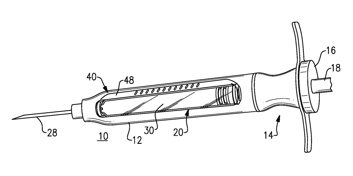
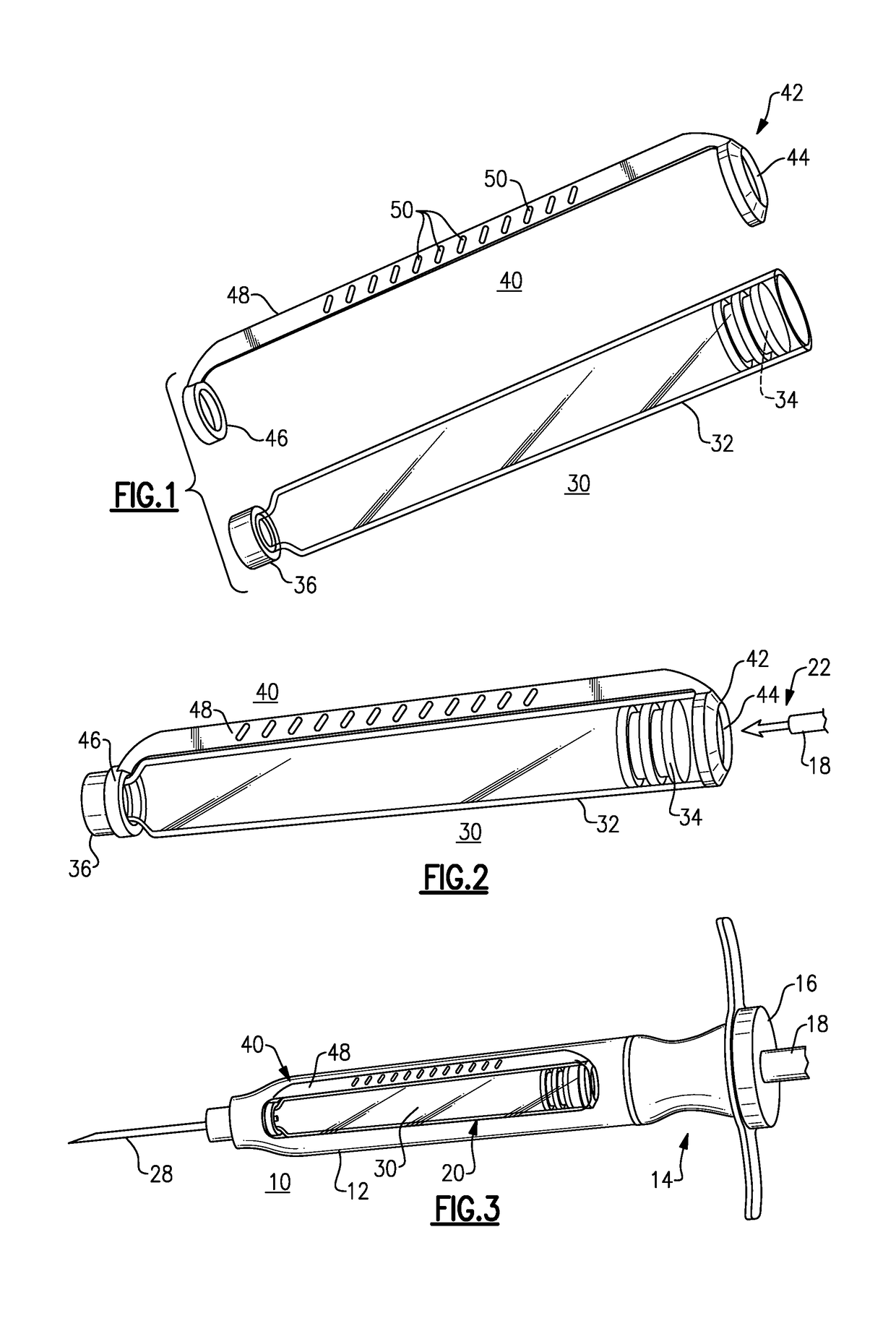
[0010]With reference to the above-listed Figures of Drawing, and initially to FIGS. 1 to 3, a dental syringe 10 (seen in FIG. 1) is formed of medical-grade stainless steel and is adapted to hold a replaceable cartridge ampule, or carpule 30. The carpule fits into the barrel portion 12 of the syringe, after which the plunger portion 14 of the syringe is attached, with male threads on the barrel portion 12 fitting female threads on the plunger portion 14. The plunger portion has a plunger assembly 16 with a movable operating shaft 18, here having a thumb ring (not shown) at its proximal end. A fixed part of the plunger portion 14 has finger rests that extend radially out to the sides. The barrel portion 12 has an open window 20 formed along one side to allow the dental practitioner to observe the carpule and its contents. Here the plunger operating rod 18 is seen to have a barbed pointed end or harpoon 22 (FIG. 2) supported at the distal end of the rod 18, the harpoon 22 being the por...


PUM


Abstract

A device or arrangement for a carpule for a dental syringe permits the harpoon on the distal end of the plunger rod to engage the rubber or rubber-like plug or piston of the carpule, but blocks the piston from being pulled out the open proximal end of the tubular glass body of the carpule. A preferred version has an apertured cap that fits onto the proximal end of the carpule, a retaining neck ring that fits onto the penetrable seal at the proximal end of the carpule, and a bar connecting them. The bar also serves as a grip to assist in handling the carpule.

Description

[0001]This application claims priority under 35 U.S.C. §119(e) of provisional application Ser. No. 62 / 365,009, filed Jul. 21, 2016, the disclosure of which is incorporated by reference herein.BACKGROUND OF THE INVENTION[0002]This invention is directed to a dental syringe and carpule, of the type used to administer a local anesthetic or other medication to a dental patient. The carpule, containing anesthetic, for example, is inserted into the barrel of the syringe, and a needle on the distal end of the syringe pierces a puncturable seal on the carpule. The plunger of the syringe contacts a rubber or rubber-like piston that can be pushed forward to eject the anesthetic solution into the patient's gum or jaw.[0003]In most current syringes, the plunger has a barbed member, i.e., a “harpoon” at its distal end and the harpoon pierces and engages the piston. This permits the dental practitioner to pull back on the plunger to withdraw the piston proximally, which causes the syringe to aspir...

Claims


Application Information

Patent Timeline
IPC IPC(8): A61M19/00A61M5/315A61M5/31A61M5/24
CPCA61M19/00A61M5/2466A61M5/31501A61M5/3137A61M2005/3139A61M2210/0625A61M2005/2474A61M2005/2485A61M2210/0631A61M5/24A61M5/31515A61M2005/2414A61M2005/5073
Inventor JEAN-CHARLES, GERMAINKASHI, AJAY RAMESH
Owner JEAN CHARLES GERMAIN
Why Eureka
Try Eureka