
Protective cover for a dental syringe needle

a protective cover and syringe technology, applied in the field of dental syringes, can solve the problems of inability to protect the operator from blood-borne infections, the operator is exposed to any blood-borne infection, and the hand holding the cap is stuck, etc., and achieves the effect of avoiding blood-borne infections, avoiding blood-borne infections, and avoiding blood-borne infections

Active Publication Date: 2021-07-06
VERENA SOLUTIONS LLC
View PDF24 Cites 2 Cited by
  • Summary
  • Abstract
  • Description
  • Claims
  • Application Information

AI Technical Summary

Benefits of technology

The invention is a method of using a needle assembly for dental procedures. The needle cap is connected to the cylindrical body of the syringe with ribs that create friction to prevent the cap from rotating during use. The cap can be rotated to change the position of the needle, and a lock tab on the hub ensures that the needle moves in the same direction as the syringe. This design allows for easier handling and reduces the risk of accidental pricks during dental procedures.

Problems solved by technology

The danger of an infectious needle stick occurs when the protective needle cap is replaced on the needle, post injection, which is now contaminated with the patient's blood and saliva.
If the needle misses the opening in the cap, there is a significant chance that the hand holding the cap will be stuck and the operator exposed to any blood-borne infection carried by the patient.
However, this recommendation is impractical in the context of dental care.
These techniques work, but they are awkward at best, allow for the risk of picking up spatter, which might have fallen onto the dental tray and often ignored out of convenience.
While this method is commonly taught in dental schools, it is rarely used by tenured dentists in favor of the two-handed technique.
Under tightening of the needle and syringe negates the protective features of the cover, as the cover, needle, and / or syringe may become disconnected during use, exposing the patient or dental caregiver to prick risk.
Particularly, in dental syringes, where the needle must be removed from the syringe after use, overtightening can require over-exertion to remove the protective cover and needle after use, which may cause a needle stick through device misoperation, breakage, or failure.

Method used


Image

  • Protective cover for a dental syringe needle
  • Protective cover for a dental syringe needle
  • Protective cover for a dental syringe needle

Examples


Embodiment Construction

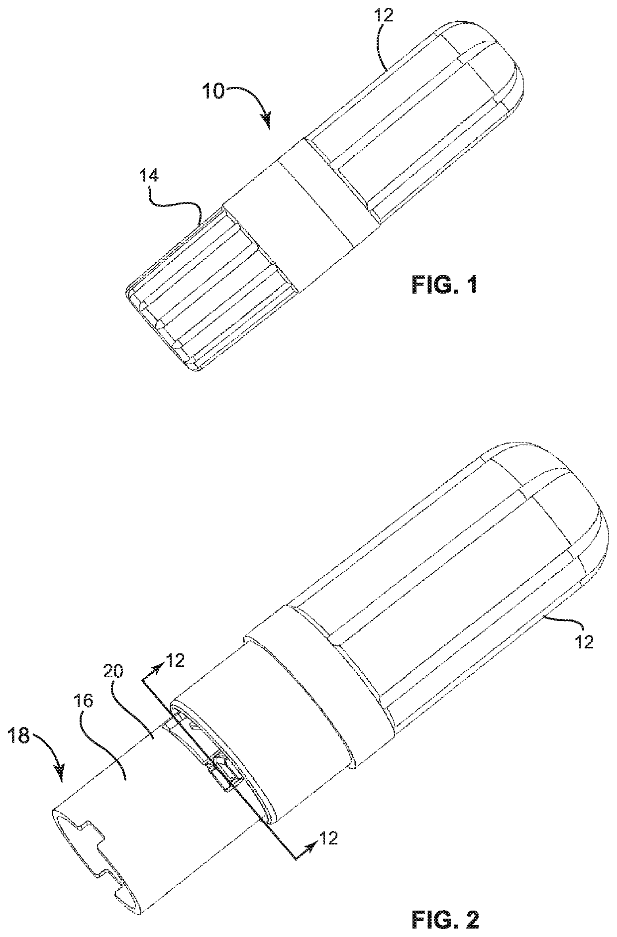
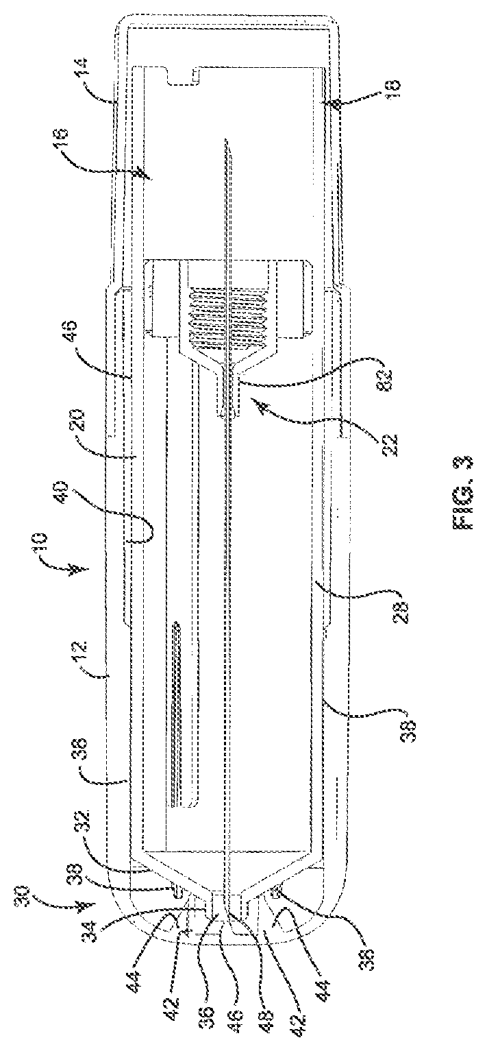
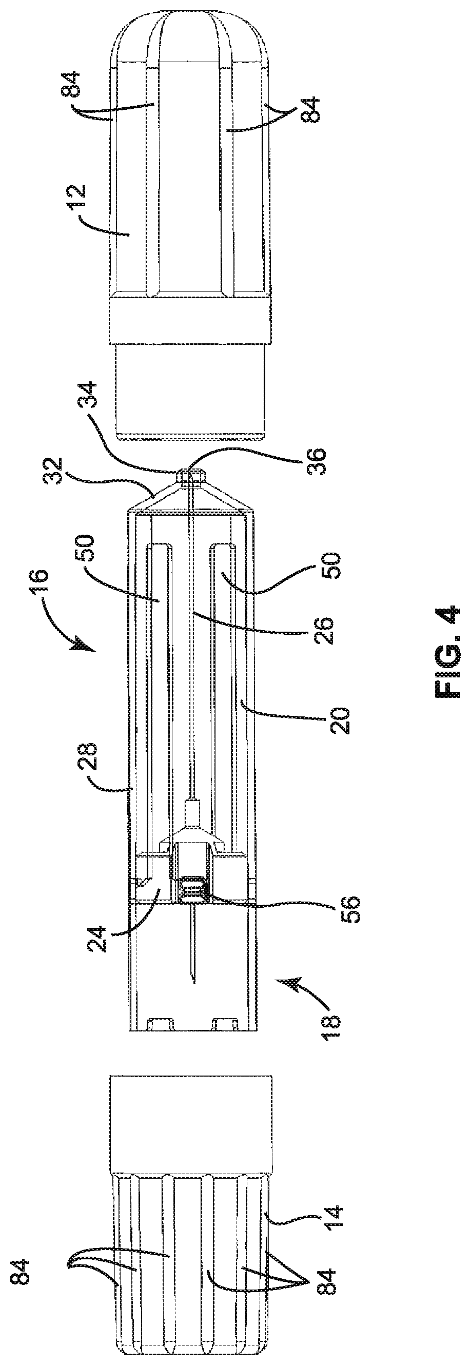
[0029]FIG. 1 depicts an exemplary embodiment of a capsule 10 that surrounds and encloses a protective dental needle as will be described in further detail herein. The capsule 10 is exemplarily formed in two parts with a needle cap 12 that surrounds an injection side of a protective dental needle and a hub cap 14 that surrounds a syringe side of the protective dental needle. The needle cap 12 and the hub cap 14 are resiliently secured together, for example by way of a friction or interference fit between the needle cap 12 and the hub cap 14. The interference fit between the needle cap 12 and the hub cap 14 creates a barrier to the environment out side of the capsule 10 about the protective dental needle. This maintains the protective dental needle in a sterile condition in which the protective dental needle is manufactured.

[0030]FIG. 2 provides the same image as FIG. 1, but with the hub cap 14 removed to expose a portion of the protective dental needle 16. Specifically, removal of th...


PUM


Abstract

A protective dental needle includes a sheath having a cylindrical body with a channel along the cylindrical body. A needle assembly includes a hypodermic needle extending through a hub. The needle assembly is retained within the sheath and movable within the sheath between a retracted position and an extended position. A needle cap is positioned external to the sheath. The needle cap includes a plurality of longitudinal ribs that extend from an interior surface of the needle cap.

Description

BACKGROUND[0001]The present disclosure relates generally to dental syringes and more specifically to a protective cover for a dental syringe needle, which reduces the risk of injury due to accidental needle pricks.[0002]Localized anesthesia minimizes the pain felt by the patient and may make the patient more compliant to receive medical treatment. While the patient is under the effects of anesthesia, the medical professional has more freedom to operate about the patient, resulting in a faster procedure.[0003]The syringes used to administer local anesthetics use a disposable cartridge of local anesthetic and a disposable needle, which attaches to an end of the syringe. The disposable needle is supplied by the manufacturer with a two part protective cover. The back part of the cover fits over the mounting hub of the needle and extends one centimeter past a back end of the front cover and is removed when the syringe is loaded for use. The front portion remains as a protective cover to ...

Claims


Application Information

Patent Timeline
Patent Type & Authority Patents(United States)
IPC IPC(8): A61M5/32
CPCA61M5/3202A61M5/3293A61M2202/048A61M2205/581A61M2210/0625A61M5/3271A61M2005/3247
Inventor INFANGER, MICHAELCARVAJAL, MICHAEL A.
Owner VERENA SOLUTIONS LLC
Learn More