Dental cortical plate alignment platform

a technology for aligning platforms and dentinoids, which is applied in the field of dentinoids, can solve the problems of increasing the cost, affecting the success of the patient's and the threat of breaking and subsequent successful retrieval of all foreign objects

Inactive Publication Date: 2003-07-15
LVI GLOBAL
View PDF6 Cites 74 Cited by
  • Summary
  • Abstract
  • Description
  • Claims
  • Application Information

AI Technical Summary

Benefits of technology

It is further accordingly an object of the present invention to provide a guidance channel exterior to the cortical plate to enable the angle of entry through the bone to be maintained as the penetrating drill passes through the bone, lessening the danger of breakage.
It is further accordingly an object of the present invention to provide a guidance channel exterior to the cortical plate to enable successful re-entry of the orifice by aligning the medicating needle tip back to the correct location, lessening trauma to the gingiva.
It is further accordingly an object of the present invention to provide a guidance channel exterior to the cortical plate to enable the angle of entry through the bone to be maintained as the medicating needle is subsequently inserted through the bone, lessening the danger of breakage.
It is further accordingly an object of the present invention to provide a guidance channel exterior to the cortical plate to provide a short protruding stem to grasp and remove should breakage of the drill, needle, or delivery device occur, lessening the danger of drills, needles, or delivery devices being broken flush to the cortical plate and slightly beneath the gingiva.
It is further accordingly an object of the present invention to provide a guidance channel exterior to the cortical plate to provide a precise predetermined angle of entry such as 29 degrees to the perpendicular, increasing success in the rear molar regions.
It is further accordingly an object of the present invention to provide a guidance channel exterior to the cortical plate while providing a visual aid herein termed a whisker to assist the dentist in maintaining a precise predetermined angle of entry such as 29 degrees to the perpendicular, decreasing incidents of breakage in the rear molar regions.

Problems solved by technology

However, difficulties as taught by Dillon mainly involving failures of re-entry caused the industry to respond with two U.S. Pat. No 5,762,639 by Gibbs, and U.S. Pat. No. 5,779,708 by Wu, both describing methods to leave an intraosseous channel in place subsequent to drilling.
Adversely, the necessity of hollow guidance sleeves to themselves be drills increased the expense over Dillon and introduced dangers involving incidents of breakage of the tiny-diameter, hollow implements.
The threat of the breakage and subsequent successful retrieval of all foreign objects from the patient is complicated by the presence as taught by Gibbs and Wu of other separate and intricate inner plugging stylets or rods.
Also the health of the patient is subsequently put at risk by the open channel, which in some cases puts bacteria in open contact with the tissues beneath the bone for several hours.
Thus the introduction of bacteria from the air or contaminated water lines, the post recovery after inevitable failure of some instruments, and the more complicated nature of drill construction has dampened the success of the latter two patents.
But the original complaint of difficult re-enty (for the Stabident system and other related prior art teaching such as the Villette injector) remains as a drawback for optimized delivery of medication.
Another pertinent negative to all three patents mentioned is the fact breakage of the drill or apparatus is prone to happen flush to the cortical plate.
The patient may waver, the Dentist may move improperly, or the fabricating material may fail.
The ability to retrieve the broken material is thus a serious issue.
Otherwise as is sometimes the case in intraosseous drilling, a crowded, curved, or deformed root may be struck with subsequent unwarranted damage to the ligaments or to the tooth itself, exposing it to infection.
Current methods of alignment are not typically done with an indexed system, which often defeats the precise placement the expensive digital imagery requires.

Method used


Image

  • Dental cortical plate alignment platform
  • Dental cortical plate alignment platform
  • Dental cortical plate alignment platform

Examples


Embodiment Construction

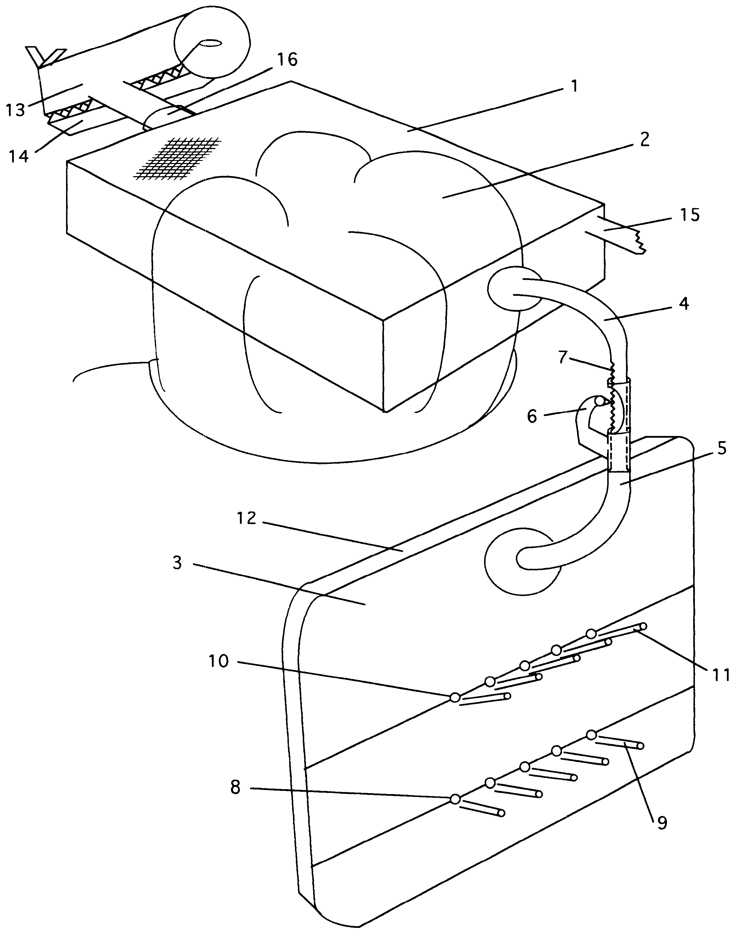
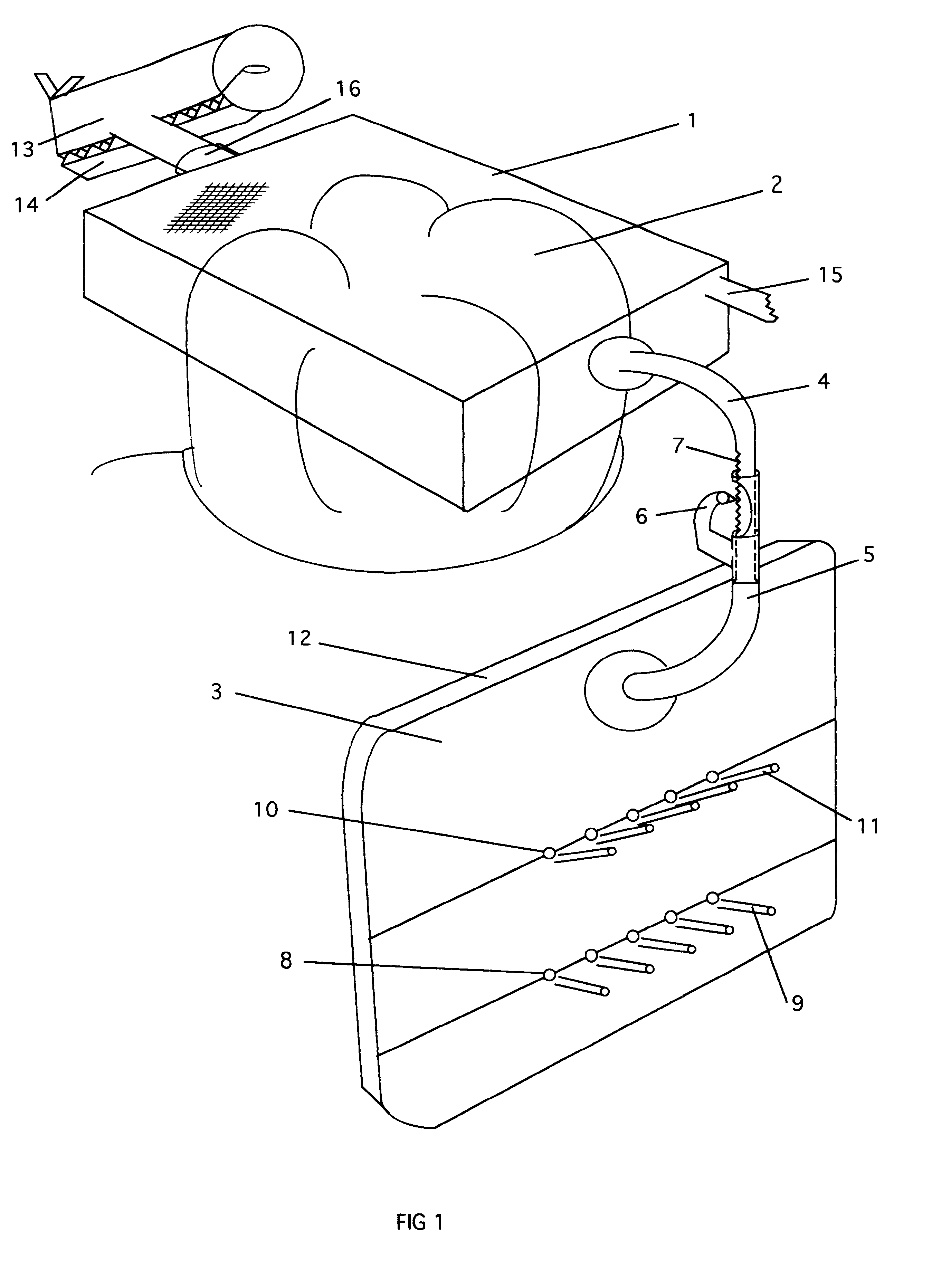
FIG. 1 bite block 1 is shown in transparent outline form over a lower left molar 2 of a patient. As seen by the crosshatching, the upper surface is solid. To connect block 1 to guidance platform 3, arcing down from the facial (cheek) side is adjustment arm 4, which is positioned inside the uplifted arm 5 rising from the guidance platform itself. The flexible wedge 6 together with the serrated edge 7 of upper arm 4 creates a trombone lock which can be elevated by the Dentist about three millimeters or lowered as much as five millimeters from the initial position. In both drawings the female element 5 bearing the wedge 6 is shown attached to the platform 3, but this is one aspect of a reversible arrangement whereby the serrated male element 7 could have been at the terminal end of the arm connected to the platform with arm 5 connected to the bite block.

A line of horizontal drilling ports 8 are positioned about ten to twelve millimeters below the crown of molar 2, which automatically p...


PUM


Abstract

This application relates to a dental apparatus for the initial and subsequent guidance of drills, hypodermic needles, or drug delivery devices into the cortical plate of human mandibular and maxillary bones. The invention comprises a thin platform with one or a plurality of angled or straight preformed perforations serving as entrance ports. Each port is optimally heralded by a radio-opaque marker to enable a view of the tooth root prior to drilling for a superior selection of a nerve deadening site and a whisker tubule visually displaying the drill's angle. The platform can be positioned on either the inner or outer side of the cortical plate, and is optimized for use with a dedicated indexing bite apparatus, a dedicated rubber dam style clamp, or by attachment to a RINN positioner or the like.

Description

This application relates to the field of medicine, and more specifically involves corrective measures to improve the success of intraosseous medication injections in Dentistry and related fields requiring anaesthesia.DISCUSSION OF THE PRIOR ARTThe art of deadening pain for the Dental industry was greatly improved by the discovery that smaller and more effective dosages of medication could be introduced beneath the cortical plate. Pivotally, U.S. Pat. No. 5,173,050 by Dillon in 1992 cited methods of and implements for drilling an initial perforation, thus allowing the dentist to remove the drill and re-enter the passageway with a hypodermic needle to deliver anaesthesia.However, difficulties as taught by Dillon mainly involving failures of re-entry caused the industry to respond with two U.S. Pat. No 5,762,639 by Gibbs, and U.S. Pat. No. 5,779,708 by Wu, both describing methods to leave an intraosseous channel in place subsequent to drilling. This channel served as a guidance system ...

Claims


Application Information

Patent Timeline
Patent Type & Authority Patents(United States)
IPC IPC(8): A61B17/16A61B17/17A61C1/08A61B17/34A61C9/00A61B19/00
CPCA61B17/176A61C1/082A61B17/3472A61B19/54A61B2019/5416A61C9/00A61C2201/002A61B90/39A61B2090/3916
Inventor WEATHERS, JR., ARTHUR K.
Owner LVI GLOBAL
Why Eureka
Try Eureka