
Needle tip guard for percutaneous entry needles

a technology of percutaneous entry and needles, applied in the field of needle tip guards for percutaneous entry needles, can solve the problems of increasing the odds of disease transmission from patient to healthcare worker, the presence of any of these pathogens in patients poses a risk to healthcare workers, and the unprecedented occupational hazards of healthcare workers

Inactive Publication Date: 2009-05-19
B BRAUN MELSUNGEN AG
View PDF221 Cites 72 Cited by
  • Summary
  • Abstract
  • Description
  • Claims
  • Application Information

AI Technical Summary

Benefits of technology

The present invention provides a safety hypodermic needle apparatus that can cover the sharp tip of the needle after use, preventing any accidental sticks or punctures. The apparatus is automatic or semi-automatic in its use, conforming to existing procedures for aspirating medication into a syringe, inserting a needle, and vascular access or catheter insertion. It allows for unrestricted access for bevel-up needle viewing and is compatible with various needle types and procedures. The apparatus is low-cost, fail-safe, and single-use in nature. It can be manufactured using automated methods and is easy to assemble and disassemble. It provides a deformable retaining means for a protective cover and can be used with long needles or needles with a change in axis at the distal tip. The apparatus is designed to minimize any mechanical resistance or fatigue from stored energy components and to leave the delicate needle tip untouched during assembly procedures. It reduces the number of components to the lowest possible number needed for the healthcare industry. It also allows for the use of a protective cover with a needle that is bent or straight, and can be retrofitted to existing needle hubs.

Problems solved by technology

The advent of Human Immunodeficiency Virus (HIV), combined with the increasing incidence of other bloodborne pathogens such as Hepatitis B Virus (HBV) and Hepatitis C Virus (HCV), present healthcare workers with an occupational hazard unprecedented in modern medicine.
The presence of any of these pathogens in patients poses a risk to healthcare workers when invasive procedures are performed.
As the population of infected individuals increases, more people will be treated by healthcare workers, further increasing the odds of disease transmission from patient to healthcare worker.
Early data suggests improper infection control techniques contribute directly to this increase: including improper use of hypodermic equipment, multiple-dose medicine vials; and failure to change protective gloves and gear for each new patient.
Recent studies also cite the discovery of significant blood contamination on re-usable blood collection vacuum tube holders which are routinely used to collect blood from different patients.
Nurses and other healthcare personnel are routinely injured by the exposed, sharp lancet of the needle after use on a patient.
A needlestick injury now carries a life-threatening consequence and healthcare workers must live with this terror on a daily basis.
In each and every instance, whether medical or industrial, exposed needles pose a danger of injuring the user.
In medicine, in addition to the danger of contacting contaminated blood or bodily fluids, highly reactive or toxic substances are used for chemotherapy or therapeutic purposes.
The basic problem with many of the present day safety hypodermic devices is that they are meant to be manually activated, or in the language of the medical device industry, they are considered “active” devices.
Although there are a number of retractable needle into syringe devices available, the manufacturing costs associated with these devices are prohibitively high.

Method used


Image

  • Needle tip guard for percutaneous entry needles
  • Needle tip guard for percutaneous entry needles
  • Needle tip guard for percutaneous entry needles

Examples


Embodiment Construction

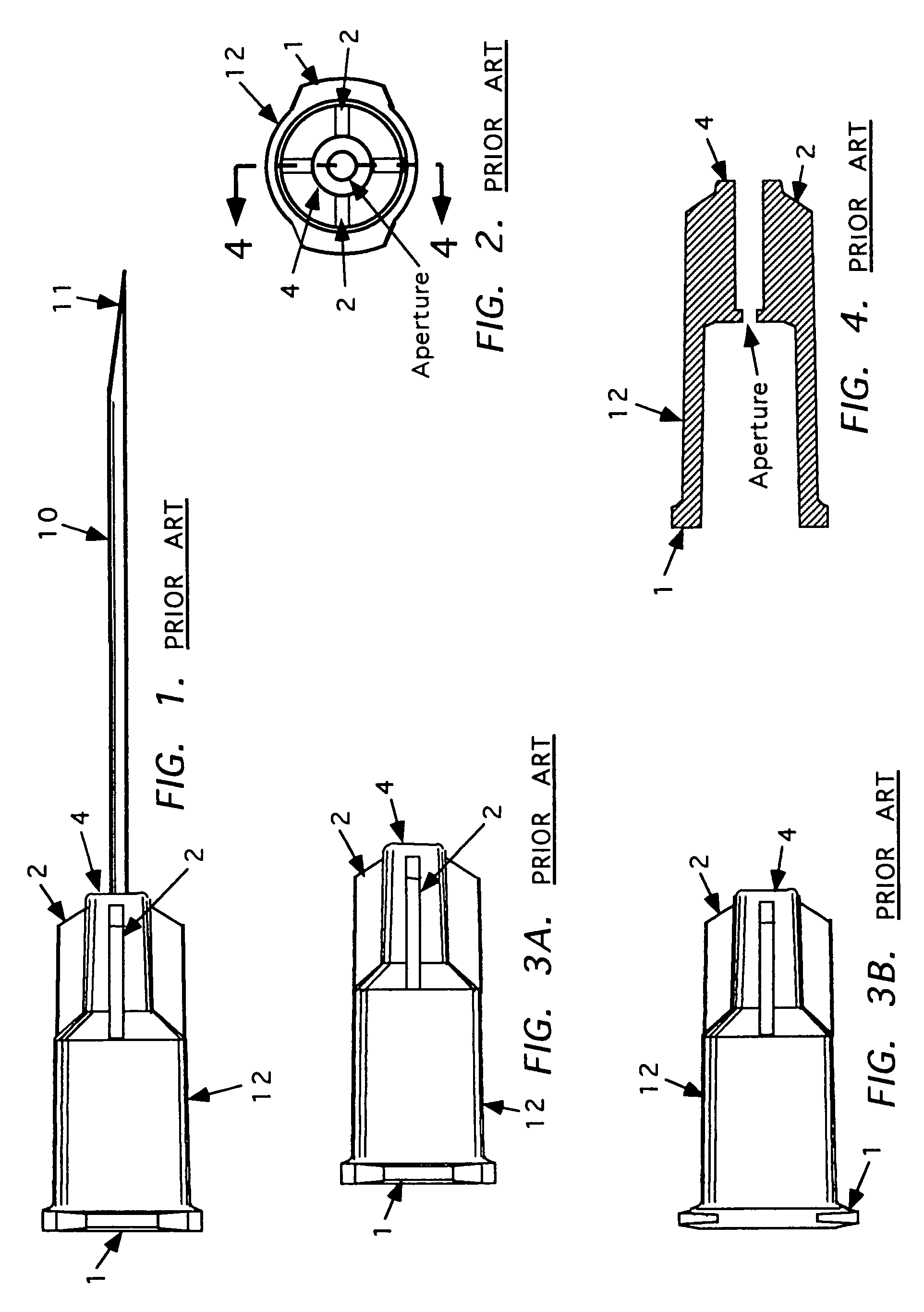
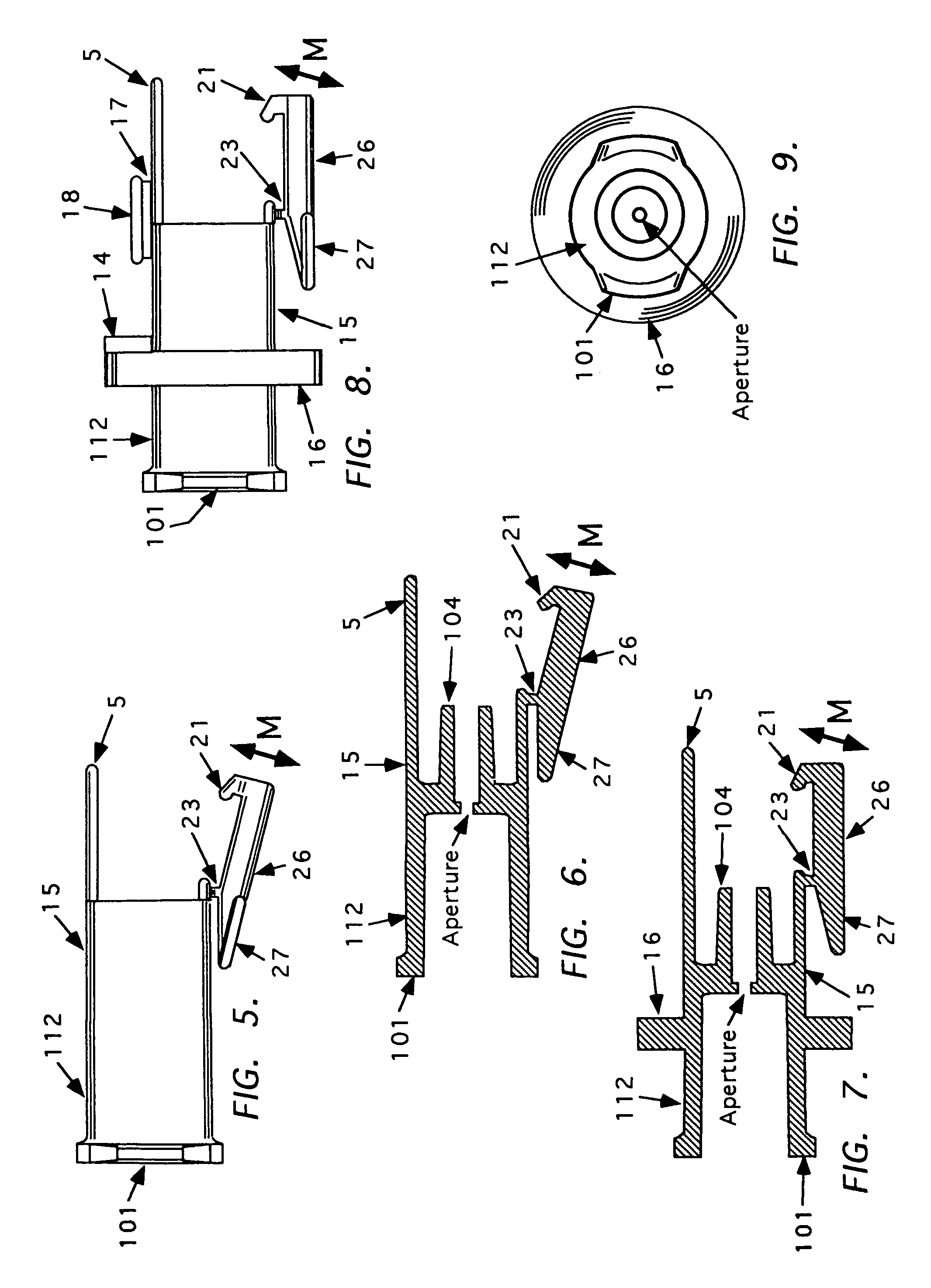
[0145]A needle tip protective device is described. In this regard, to the extent applicable, this application is related to and claims the benefit of filing dates of the following U.S. Non-Provisional patent applications: (1) Ser. No. 60 / 012,343, entitled PROTECTED HYPODERMIC NEEDLE WITH AUTOMATIC AND MANUAL COVERING MEANS, filed Feb. 27, 1996; (2) Ser. No. 60 / 025,273, entitled HYPODERMIC DEVICES WITH SAFETY FEATURES, filed Sep. 12, 1996; and (3) Ser. No. 60 / 031,399, entitled HYPODERMIC DEVICES WITH IMPROVED SAFETY FEATURES, filed Nov. 19, 1996; (4) U.S. patent application Ser. No. 08 / 807,328 entitled NEEDLE TIP GUARD FOR HYPODERMIC NEEDLES, now issued as U.S. Pat. No. 5,879,337; (5) U.S. patent application Ser. No. 09 / 172,185 entitled INTRAVENOUS CATHETER ASSEMBLY, now issued as U.S. Pat. No. 6,001,080, filed on Oct. 13, 1998; and U.S. patent application Ser. No. 09 / 144,398 entitled NEEDLE TIP GUARD FOR HYPODERMIC NEEDLES, filed on Aug. 31, 1998, the teachings of which are expressl...


PUM

PropertyMeasurementUnit
disease transmissionaaaaaaaaaa
timeaaaaaaaaaa
lengthsaaaaaaaaaa

Abstract

A needle tip protective device for use with percutaneous entry needles. In one embodiment, the needle tip protective device includes a needle guard slidably mounted on a hypodermic needle, the latter having a needle tip located at the distal end thereof, and a change of profile formed medially there along. The needle guard is movable along the hypodermic needle and engageable with the change in profile formed thereon. The engagement with the change in profile is configured to correspond with the ability of the needle trap to entrap the needle tip once the needle trap has advanced the sufficient distance distally along the hypodermic needle. In further refinements, the needle trap may be biased toward the distal needle tip of the needle.

Description

CROSS-REFERENCE TO RELATED APPLICATIONS[0001]This application is related to and claims the benefit of filing dates of the following U.S. Non-Provisional patent applications: (1) Ser. No. 60 / 012,343, entitled PROTECTED HYPODERMIC NEEDLE WITH AUTOMATIC AND MANUAL COVERING MEANS, filed Feb. 27, 1996; (2) Ser. No. 60 / 025,273, entitled HYPODERMIC DEVICES WITH SAFETY FEATURES, filed Sep. 12, 1996; and (3) Ser. No. 60 / 031,399, entitled HYPODERMIC DEVICES WITH IMPROVED SAFETY FEATURES, filed Nov. 19, 1996; (4) U.S. patent application Ser. No. 08 / 807,328 entitled NEEDLE TIP GUARD FOR HYPODERMIC NEEDLES, now issued as U.S. Pat. No. 5,879,337; filed Feb. 27, 1997; (5) U.S. patent application Ser. No. 09 / 172,185 entitled INTRAVENOUS CATHETER ASSEMBLY, now issued as U.S. Pat. No. 6,001,080, filed on Oct. 13, 1998; (6) U.S. patent application Ser. No. 09 / 144,398 entitled NEEDLE TIP GUARD FOR HYPODERMIC NEEDLES, now issued as U.S. Pat. No. 6,443,929, filed on Aug. 31, 1998; (7) U.S. patent applica...

Claims


Application Information

Patent Timeline
Patent Type & Authority Patents(United States)
IPC IPC(8): A61M5/32A61B5/15A61M5/00A61M5/158A61M5/24A61M5/31A61M25/00A61M25/06
CPCA61B5/150572A61M5/3275A61B5/1438A61B5/154A61M25/0625A61B5/150488A61B5/150496A61B5/150389A61B5/150641A61M5/3273A61B5/15003A61B5/150732A61M5/3243A61M2005/325A61M5/329A61M5/3202Y10S128/919A61M5/3257A61M2005/2414A61M2205/583A61M25/0606A61M25/0612Y10T29/49826A61M2005/3246A61M5/002A61M5/24A61M2005/3109A61M5/3291A61M5/00
Inventor KURACINA, THOMAS COHNEMUS, RANDALL E.SMITH, CRAIG W.COHEN, RICHARDROLLO, DAVID
Owner B BRAUN MELSUNGEN AG
Learn More