Display panel having noise shielding structure

Active Publication Date: 2005-02-03
DENSO CORP
View PDF2 Cites 46 Cited by
  • Summary
  • Abstract
  • Description
  • Claims
  • Application Information

AI Technical Summary

Benefits of technology

[0010] The present invention therefore has an objective to provide a display device having a noise shielding structure that effectively shields unnecessary radiating noises. A display device of the present invention has a display panel and a metal external frame that houses the display panel. A connecting member is provided for connecting the display panel to an external device. Since this connecting member may produce unnecessary radiating noises, a shielding layer is formed on the connecting member for reducing the radiating noises. The shielding layer is electrically connected with the external frame. Because the external frame has a large surface area, it works as a stable ground and the radiating noises are effectively reduced.
[0011] The dis

Problems solved by technology

Because high-frequency control signals are inputted to the LCD panel, unnecessary radiating noises (electromagnetic waves) are produced.
Therefore, unnecessary radiating noises are produced from the FPC.
Thus, problems including noises in radio sound or television picture distortion are caused by the radiating noises produced from the liquid crystal display device.
However, this provides little effect on reduction

Method used


Image

  • Display panel having noise shielding structure
  • Display panel having noise shielding structure
  • Display panel having noise shielding structure

Examples


first embodiment

[0025] [First Embodiment]

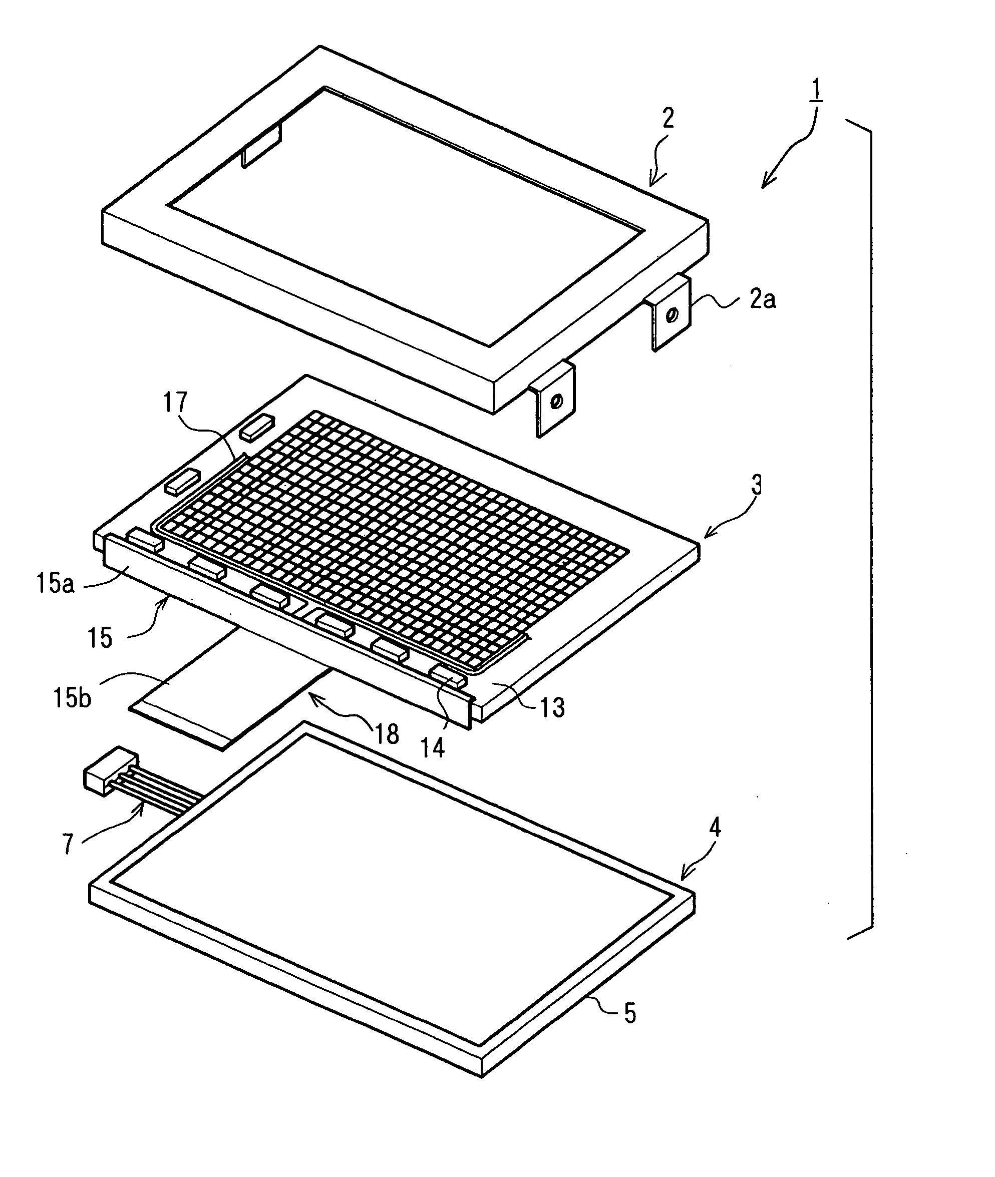
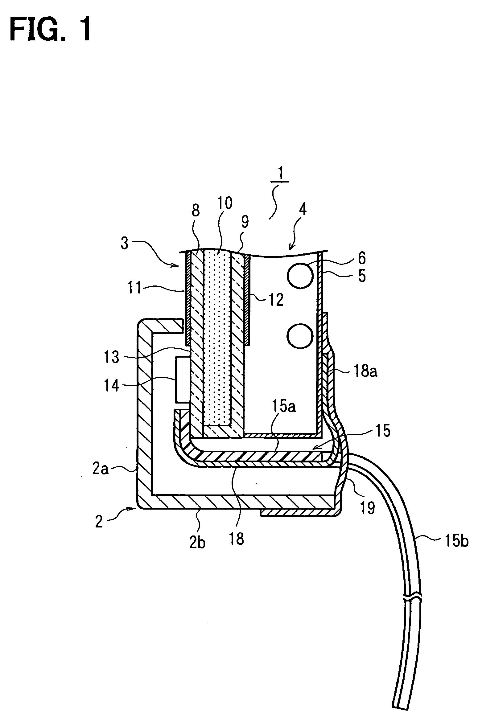
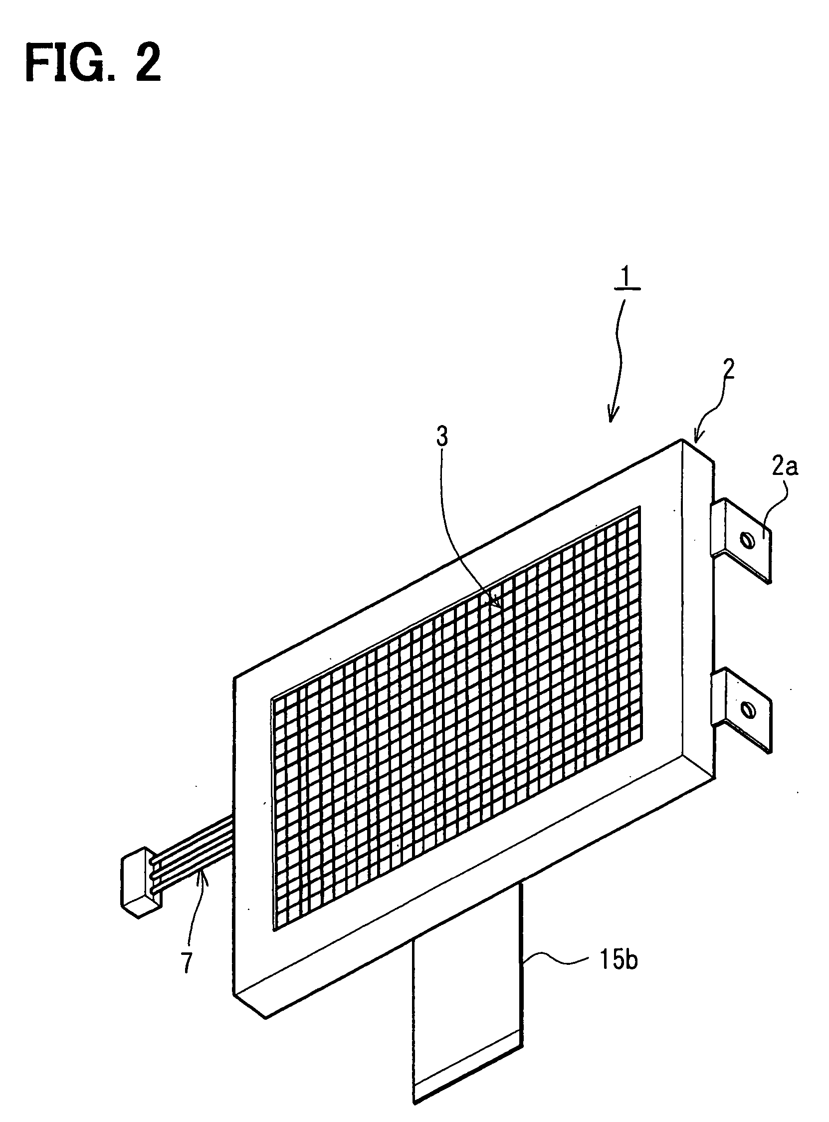
[0026] Referring to FIGS. 1 through 3, a liquid crystal display (LCD). device 1 is constructed of an external frame 2, an LCD panel 3 and a backlight unit 4. The LCD panel 3 and the backlight unit 4 are arranged in layers and housed in the external frame 2 made of a metal plate, such as a steel plate. The backlight unit 4 having a light source 6 in an outer case 5 is positioned at a posterior part of the external frame 2. A cable 7 for connecting the light source 6 to a power source is extended from the backlight unit 4.

[0027] The LCD panel 3 is constructed by filling liquid crystal 10 between first and second glass substrates 8, 9 and positioned at an anterior part of the inside space of the external frame 2. The first glass substrate 8 is located in the front while the second substrate 9 is located in the rear. Deflecting plates 11, 12 are arranged in display areas of a front surface of the first glass substrate 8 and a rear surface of the second glass su...

second embodiment

[0045] [Second Embodiment]

[0046] Referring to FIG. 7, the LCD panel 3 has two different sizes of transparent plates21, 22, one of which is a glass substrate 22. Other components of the LCD device 1 are the same as the first embodiment and assembled in the same manner as the first embodiment. The first glass substrate 21 located in the front is smaller than the second glass substrate 22 located in the rear. An outer area of the second glass substrate 22 around its display area is not covered by the. first glass substrate 21, namely, exposed to the outside. This outer area is referred to as a circuit board area 23. Circuit patterns (not shown) are formed in the circuit board area 23 on the front surface of the second glass substrate 22 and the driver ICs 14 are mounted.

[0047] The FPC 15 is prepared in the same manner as the first embodiment and connected with the second glass substrate 22. With this configuration, the radiating noises are effectively reduced as discussed in the first...

third embodiment

[0048] [Third Embodiment]

[0049] Referring to FIG. 8, an external frame 200 houses the LCD panel 3 and the backlight unit 4. It has a bump portion 24 that inwardly protrudes from a bottom portion 2b. The FPC 15 is prepared and connected with the LCD panel 3 in the same manner as the first embodiment. The bump portion 24 is brought into contact with or bonded to the metal foil 18. As a result, the metal foil 18 is electrically connected with the external frame 200. Since the metal foil 18 is electrically connected with the external frame 200, the radiating noises are effectively reduced as discussed in the first embodiment section.


PUM


Abstract

A circuit board area is formed on a front glass substrate of a liquid crystal display (LCD) panel, and driver ICs are mounted in the circuit board section. The driver ICs are electrically connected to an external display control device via a flexible printed circuit board (FPC). A metal foil is attached to one side of the FPC for shielding unnecessary radiating noises. The metal foil has connecting flap portions and the flap portions are fixed to an outer case of a backlight unit with a metal foil tape. The metal foil tape is also bonded to an external frame of an LCD device. As a result, the metal foil is electrically connected with the external frame and the radiating noises are effectively reduced.

Description

CROSS REFERENCE TO RELATED APPLICATION [0001] This application is based on and incorporates herein by reference Japanese Patent Application No. 2003-284092 filed on Jul. 31, 2003. FIELD OF THE INVENTION [0002] The present invention relates to a display panel having a noise shielding structure. BACKGROUND OF THE INVENTION [0003] A liquid crystal display (LCD) used in a vehicle for displaying a map for. vehicle navigation or a television program. The LCD includes an LCD panel, a backlight unit, and an external frame as main components. The external frame houses the LCD panel and the backlight unit. The LCD panel is constructed of two transparent plates and liquid crystal that is filled between the transparent plates. In recent years, glass substrates are used for the transparent plates. Circuit patterns are formed on the glass substrate outside a display area by print wiring means. A driver IC for the LCD panel is mounted in the circuit pattern formed area. In such a display, the circ...

Claims


Application Information

Patent Timeline
IPC IPC(8): G02F1/13G02F1/1345G02F1/1333G09F9/00H05K1/02H05K3/36H05K9/00
CPCG02F1/133308G02F1/13452H05K3/361H05K1/0218G02F2001/133334G02F1/133334G02F1/1306H05K9/00G02F1/1333
Inventor SUZUKI, ISAMU
Owner DENSO CORP
Why Eureka
Try Eureka