Multi-blade fan
A multi-blade and fan technology, which is applied to the components of pumping devices for elastic fluids, non-variable-capacity pumps, machines/engines, etc., can solve the problems of insufficient suppression effect of impeller 5 and large eddy currents.
- Summary
- Abstract
- Description
- Claims
- Application Information
AI Technical Summary
Problems solved by technology
Method used
Image
Examples
no. 1 approach
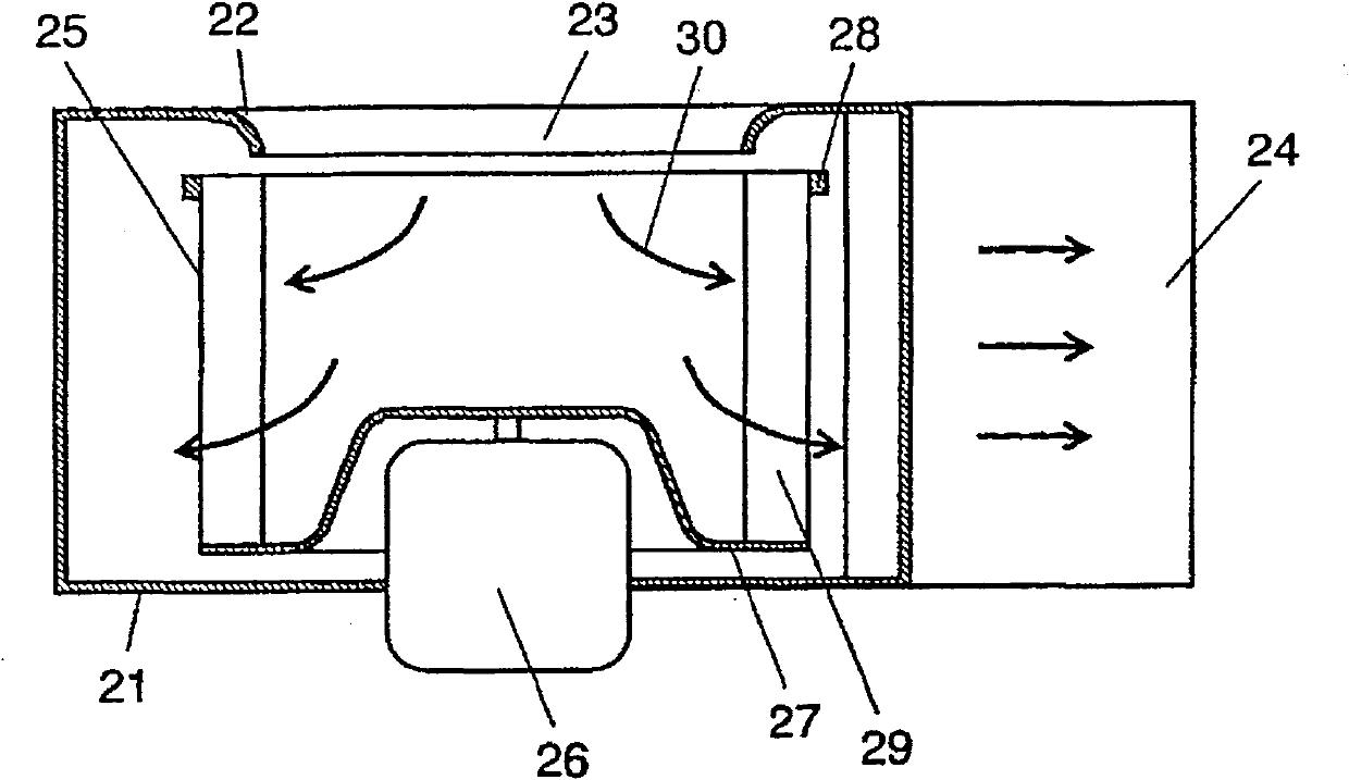
[0026] figure 1 It is an overall configuration diagram of the multi-blade fan according to the first embodiment of the present invention. The casing 21 has a spiral shape, has a flared orifice 22 formed on one side of the central portion, and has a suction port 23 and a discharge port 24 . An impeller 25 is arranged inside the casing 21 and is driven by a motor 26 . The impeller 25 includes a plurality of blades 29 supported at both ends in the axial direction by a main plate 27 and a side plate 28 . The air sucked in from the suction port 23 is guided to the air supplied to the impeller 25 as an inflow 30 as indicated by an arrow.
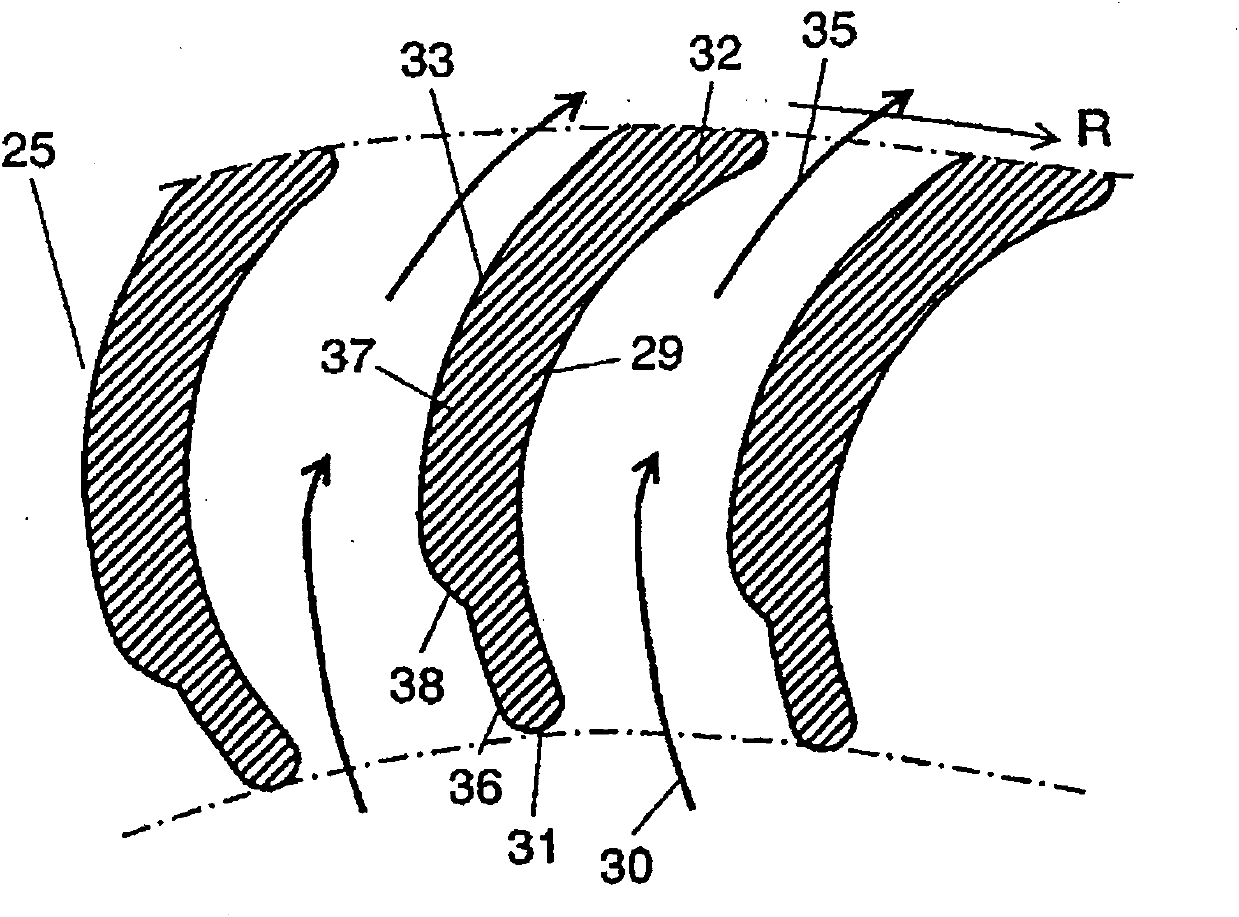
[0027] figure 2 A cross-sectional view in a direction perpendicular to the rotation axis of the blade 29 is shown. As for the blades 29, a plurality of blades 29 of the same shape are spaced apart at equal intervals and arranged in a ring shape. Each blade 29 has a shape as shown in the figure, has a leading edge 31 and a trailing edge 32 ,...
no. 2 approach
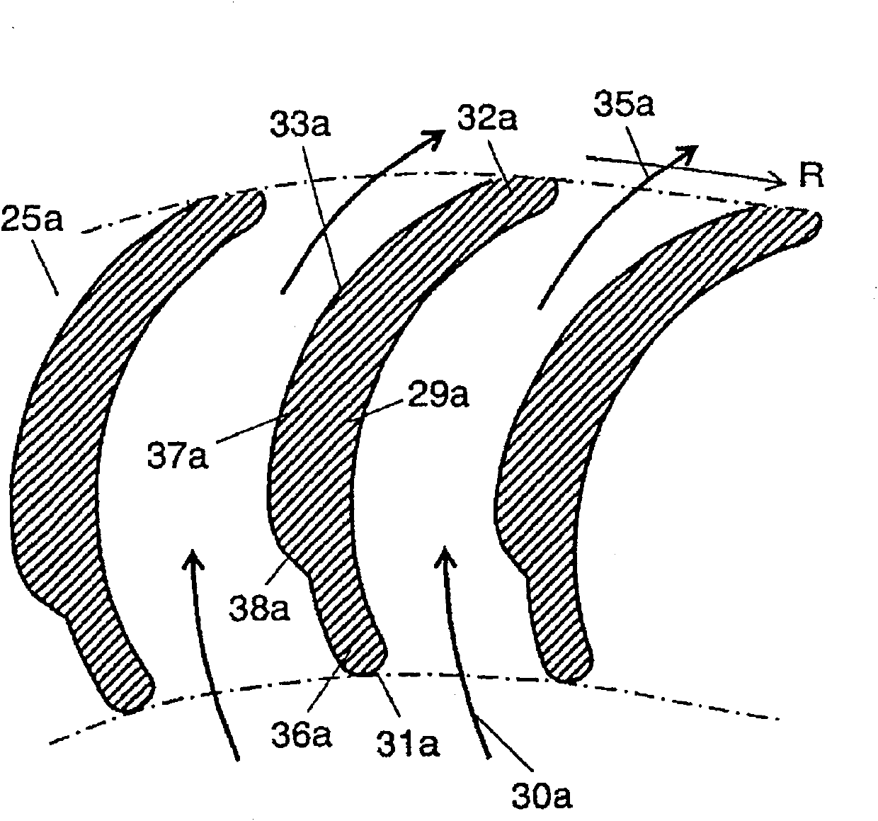
[0034] image 3 It is a cross-sectional view of the blade 29a of the multi-blade fan according to the second embodiment of the present invention. In addition, the same numerals are assigned to the same parts as those in the first embodiment, and detailed description thereof will be omitted.
[0035] The air guided by the orifice 22 flows in the form of the inflow 30a and the outflow 35a as shown by the arrows, but the stripping vortex at the back surface 33a is suppressed by the prescribed shape of the back surface, thereby reducing the generation of eddies and reducing turbulence. effect of noise.
[0036] Such as image 3 As shown, the shape of the back surface of the cross section perpendicular to the rotation axis of the blade 29a is formed into a predetermined shape so that the main flow flows along the blade back surface 33a from the leading edge 31a toward the trailing edge 32a of the blade 29a. That is, the shape of the back surface 33a has a thin-walled portion 36a...
no. 3 approach
[0041] Figure 4It is a perspective view of the main part of the multi-blade fan according to the third embodiment of the present invention. In addition, the same numerals are assigned to the same parts as those of the first embodiment or the second embodiment, and detailed description thereof will be omitted.
[0042] Such as Figure 4 As shown, the impeller 25b includes a plurality of blades 29b supported at both ends in the axial direction by a main plate 27b and side plates 28b. The blade 29b is set in a predetermined shape with a predetermined length L1 in the axial direction from the main plate 27b. Here, the predetermined length L1 is not more than two-thirds and not less than one-third of the axial length of the blade 29b.
[0043] The predetermined shape of the predetermined length L1 is the same as the first embodiment, and the shape of the back surface has a thin portion 36b and a thick portion 37b from the front edge 31b toward the rear edge 32b. The thickness ...
PUM
 Abstract
Description
Claims
Application Information
 - R&D
- Intellectual Property
- Life Sciences
- Materials
- Tech Scout
- Unparalleled Data Quality
- Higher Quality Content
- 60% Fewer Hallucinations
Browse by: Latest US Patents, China's latest patents, Technical Efficacy Thesaurus, Application Domain, Technology Topic, Popular Technical Reports.
© 2025 PatSnap. All rights reserved.Legal|Privacy policy|Modern Slavery Act Transparency Statement|Sitemap|About US| Contact US: help@patsnap.com


