Architecture for guiding the air flow in a disk storage device

a disk storage device and air flow technology, applied in the direction of electrical apparatus construction details, instruments, record information storage, etc., can solve the problems of difficult to achieve low dissipation, limited rotational speed of the disk pack, internal temperature rise of the head disk assembly,

Inactive Publication Date: 2000-07-18
HITACHI GLOBAL STORAGE TECH NETHERLANDS BV
View PDF10 Cites 50 Cited by
  • Summary
  • Abstract
  • Description
  • Claims
  • Application Information

AI Technical Summary

Benefits of technology

It is another object of this invention to improve head positioning assembly resistance to flutter or buffeting caused by high speed air flow.
The present invention is a skimmer structure used to lower aerodynamic dissipation in a hard disk drive by effectively shielding the head positioning assembly from high speed air flow in the disk pack and a fairing attached to the head positioning assembly to promote laminar flow about the head positioning assembly.
Additionally, the head positioning assembly is constructed or modified to reduce the turbulence associated with conventional head positioning assemblies. A fairing is added to the head positioning assembly which promotes laminar air flow about the fairing and the head positioning assembly. Alternately, the head positioning assembly may be constructed to have a shape which promotes laminar air flow about the assembly. The fairing or integral shaping of the head positioning assembly can be used in conjunction with or independently of the skimmer structure to obtain the best results for lowering aerodynamic dissipation within the hard disk drive.

Problems solved by technology

The rotational speed of the disk pack is limited by such factors as rotational drag, and aerodynamic drag on components.
The work done by the spindle manifests itself as aerodynamic dissipation (heat) inside the head disk assembly and causes the internal temperature of the head disk assembly to rise.
Unfortunately, it is difficult to achieve low dissipation.
The resulting rise in internal head disk assembly temperature is undesirable for a number of reasons.
One reason is that increased outgassing of materials can later contribute to unfavorable head / disk interactions.
Unfortunately, flow-through type systems and the aforementioned method of venting the spindle hub sap energy from the spindle motor.
The head positioning assembly can be a major source of aerodynamic dissipation within the head disk assembly.
This partial obstruction leads to an aerodynamic wake adjacent to the trailing edge of the head positioning assembly.
The Reynolds number based on the circumferential speed, the distance between the disks, and the kinematic viscosity of the air is such that the flow between the disks is turbulent and thus unsteady.
In some head disk designs, air flow induced vibrations may exhibit an oscillation that is unstable for small amplitudes, but limited at some finite amplitude, usually by non-linear effects.
Buffeting and flutter disturb the positioning system, causing data errors to occur while reading from or writing to the disks.
In the case of thin flexible disks, aerodynamic excitation causes disk bending which can cause servo positioning errors that make it more difficult to increase track density.
However, spinning the disks faster intensifies the aerodynamic interference within the disk enclosure.

Method used


Image

  • Architecture for guiding the air flow in a disk storage device
  • Architecture for guiding the air flow in a disk storage device
  • Architecture for guiding the air flow in a disk storage device

Examples


Embodiment Construction

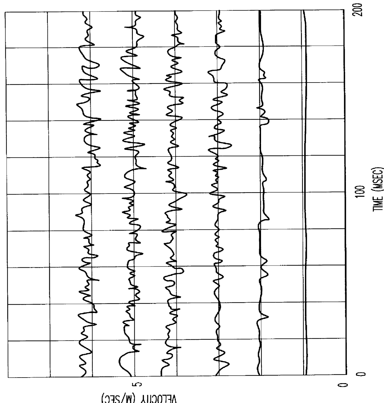
FIG. 1 is a reproduction of a photograph of an oscillographic plot of the instantaneous speed of air at the center of a preferred embodiment exhaust nozzle. In FIG. 5 this measurement is taken at a point 65.

The oscilloscope trace at the bottom of the Y-axis and extending along the X-axis of the oscillographic plot in FIG. 1 corresponds to zero air speed while the uppermost trace on the Y-axis corresponds to a mean air speed of 10 meters per second. The air speed increase between each trace is 2 meters per second.

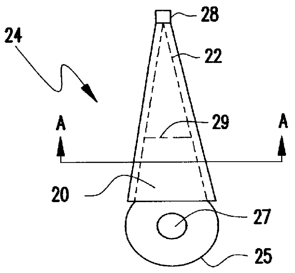
FIG. 2A shows an arm 20 and slider 28 of head positioning assembly 24 fitted with a fairing 26 that envelops arm 20, wherein suspension 22 is a flexible portion of arm 20 that extends from dashed line 29 and supports the slider 28. The arm 20 is connected to actuator 25 which pivots around point 27. The fairing 26 may be of any cross-sectional or longitudinal shape which prevents flutter or buffeting due to aerodynamic turbulence and may be attached to the head positioning a...


PUM

PropertyMeasurementUnit
mean air speedaaaaaaaaaa
air speedaaaaaaaaaa
frictionaaaaaaaaaa

Abstract

A disk drive assembly enclosed in a housing, having a head disk assembly including a spindle, disks axially attached to the spindle, a driving motor for rotating the spindle, a read / write head, and a carriage assembly including a positioning arm, slider mechanism and a actuator / suspension mechanism. The slider mechanism is slidably attached to the positioning arm and the actuator suspension mechanism is attached to the positioning arm. The read / write head for reading or writing information to the disks is attached to the head positioning assembly at the slider mechanism. A fairing is attached to the positioning arm. The head positioning assembly is enclosed within the skimmer structure. The skimmer structure has a plurality of slots for receiving the disks of the disk pack. As the disks of the disk pack pass through the slots of the skimmer structure air is stripped away from the disks.

Description

1. Field of the InventionThe invention generally relates to hard disk file units and more particularly to the configuration of a head disk unit within the hard disk file unit.2. Description of the Prior ArtConventional hard disk drives include disks that have recording tracks concentrically spaced on each disk surface. Several of these disks are stacked and mounted on a spindle and subsequently called a disk pack. The disk pack is enclosed in a clean enclosure called the disk drive housing.As the disks spin at very high speed, read / write elements or heads read information from or record information to the recording tracks on the spinning disks. Each read / write element is associated with a single disk.Typical head disk assemblies include a read / write element (read / write head) carried on a slider. The slider is suspended from a positioning arm. A servo controlled actuator system connected to the positioning arm electrically moves the slider suspended from the arm across the disk surfa...

Claims


Application Information

Patent Timeline
Patent Type & Authority Patents(United States)
IPC IPC(8): G11B33/14G11B25/04G11B17/038G11B17/02
CPCG11B25/043G11B33/148G11B17/038
Inventor HENDRIKS, FERDINAND
Owner HITACHI GLOBAL STORAGE TECH NETHERLANDS BV
Why Eureka
Try Eureka