Cannula and adapter for multifunction syringe

a multi-functional, cannula technology, applied in the field of cannulas and adapters for multi-functional syringes, can solve the problems of multi-functional syringe malfunction, high cost and time consumption, etc., and achieve the effect of convenient placement of cannulas

Active Publication Date: 2017-11-14
PROD DENTAIRES PIERRE ROLAND
View PDF10 Cites 2 Cited by
  • Summary
  • Abstract
  • Description
  • Claims
  • Application Information

AI Technical Summary

Benefits of technology

[0017]These characteristics avoid any plastics material swarf being formed while the cannula is being put into place, and also avoids any deformation of the channels projecting from the syringe. The working lifetime of the syringe is lengthened and the operations performed by the practitioner are simplified.
[0027]In an advantageous embodiment, the channels are reinforced in the proximity of the bushing, e.g. by brackets. Thus, the male channels, once engaged in the female channels, do not risk being twisted by a user seeking to detach the cannula and twisting it in untimely manner: the brackets serve to prevent any such twisting.

Problems solved by technology

The endpiece is removable but not consumable, so between two interventions, once it has been removed, it is therefore necessary for it to be cleaned and sterilized, with that naturally constituting a task that is expensive and time-consuming, while also being not entirely reliable as to its result.
Nevertheless, that system presents the drawback whereby the initial positioning of the cannula and the syringe is essentially performed only by eye by aligning the spline with the slot.
This can lead to plastics material swarf being formed that might block the channels, and possibly also to deformation of a male channel, thereby leading to malfunction of the multifunction syringe.
Nevertheless, that solution makes the cannula more complicated to put into place.
Finally, the system of document WO 92 / 04878 runs the risk of the male channels of the adapter being twisted when the cannula is removed.
Thus, depending on the positioning of the gasket, which may vary on each occasion a new cannula is put into place, and also depending on the aging state of the gasket, it can become impossible to obtain air that is completely dry.
Unfortunately, such air that is completely dry is essential in performing certain acts of dentistry, and this therefore gives rise to a significant problem in use of that equipment.

Method used


Image

  • Cannula and adapter for multifunction syringe
  • Cannula and adapter for multifunction syringe
  • Cannula and adapter for multifunction syringe

Examples


first embodiment

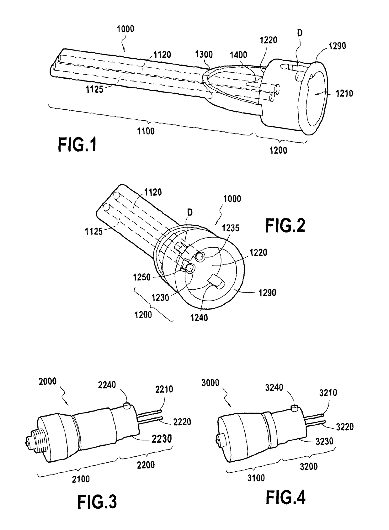
[0054]FIG. 3 shows an adapter of the invention for co-operating with the cannula 1000 shown in FIGS. 1 and 2. The adapter is made of stainless steel, or of aluminum, or indeed of synthetic resin. It is made up of two sections that are arranged consecutively in a longitudinal direction.

[0055]A first section 2100 is a section for fastening to a multifunction dental syringe. It is specific to a given type of multifunction dental syringes, as provided by a given manufacturer of dentists' chairs.

[0056]The second section, referenced 2200 is a section for fastening to a cannula of the type shown in FIGS. 1 and 2. It is generally a body of revolution, being generally cylindrical in shape, with a free end constituting a right and plane section of the cylinder. Male metal channels project from this end and are suitable for engaging in the openings 1230 and 1235 of the channels in the cannula 1000. A longitudinal slot 2230 is adapted to receive the spline 1240 of the cannula 1000.

[0057]Finally...

second embodiment

[0058]In FIG. 4, there can be seen an adapter 3000 in the invention. In similar manner to the adapter 2000 shown in FIG. 3, this adapter 3000 has a first section 3100 for enabling it to be fastened to the end of a specific multifunction dental syringe supplied by a given dentists' chair manufacturer.

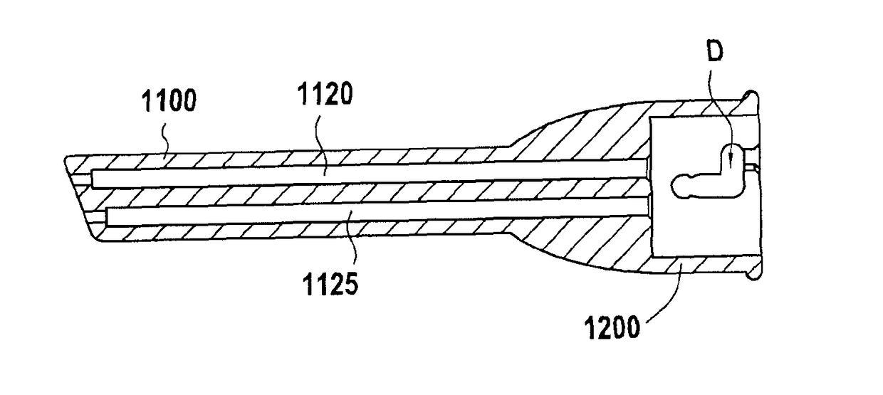
[0059]The adapter 3000 also has a section 3200 for fastening to the cannula 1000. The section 3200 is entirely similar to the section 2200 described with reference to FIG. 3.

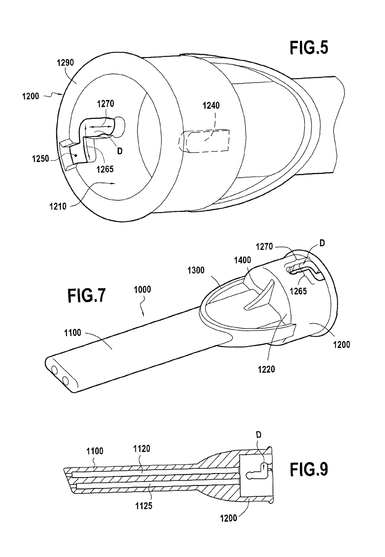
[0060]With reference to FIGS. 5 and 6, there follows a description in detail of the shape of the cutout D present in the wall of the bushing 1200. This cutout is placed approximately diametrically opposite from the spline 1240.

[0061]This cutout D begins in the section 1210 via the opening 1250, and then has a first segment of constant width extending in the longitudinal direction of the bushing. This segment is referenced 1260 in FIG. 6. It is followed by a second segment 1265 at right angles to the first segment 126...


PUM


Abstract

A cannula for a multifunction dental syringe includes a fastener bushing that is defined by a circular opening, an end wall, and a side wall comprising a circular cylinder. The cannula also includes at least two channels enabling fluids to be conveyed separately or together from the end wall to fluid projection orifices, and beginning in the end wall beside each other. The cannula is arranged so that the circular cylinder presents a cutout in the thickness of its wall. The cutout comprises, going from the opening, at least one segment extending in a direction other than the axial direction of the cylinder; followed by a longitudinal segment extending towards the end wall.

Description

TECHNICAL FIELD AND PRIOR ART[0001]The invention lies in the field of equipment and appliances for dentistry.[0002]Dentists' offices are commonly fitted with dentists' chairs that incorporate numerous instruments that are within reach of the practitioner while leaning over the patient. Among these instruments, a central element of the equipment is a syringe for projecting air, water, and an air / water mixture (multifunction syringe or air / water syringe).[0003]The function of the air / water syringe is to deliver a constant stream of the selected fluid or fluid mixture so as to enable the practitioner to rinse and dry zones in the mouth depending on how the practitioner's intervention is proceeding. When the air-only function of the syringe is used, it is particularly important for the blown air to be completely dry, so as to guarantee good quality for the intervention.[0004]Depending on the manufacturer of the dentists' chair, various different air / water syringes are in existence. Thes...

Claims


Application Information

Patent Timeline
Patent Type & Authority Patents(United States)
IPC IPC(8): A61C17/00A61C17/02
CPCA61C17/00A61C17/0202
Inventor FOURNIE, MARGUERITESAUROU, SABRINA
Owner PROD DENTAIRES PIERRE ROLAND
Why Eureka
Try Eureka