Surgical Stapling Instrument Having An Improved Coating

Inactive Publication Date: 2014-01-16
CILAG GMBH INTERNATIONAL
View PDF6 Cites 639 Cited by
  • Summary
  • Abstract
  • Description
  • Claims
  • Application Information

AI Technical Summary

Problems solved by technology

Otherwise, opposing jaws may be drawn too close together, especially pinching at their distal ends, and thus not effectively forming closed staples in the severed tissue.
At the other extreme, an excessive amount of clamped tissue may cause binding and an incomplete firing.
In addition, some surgeons, not familiar with the larger staple cartridges, may become concerned that binding or other malfunction has occurred when an unexpectedly higher force is required.
These known surgical stapling instruments with multiple-stroke firing mechanisms do not have the advant

Method used


Image

  • Surgical Stapling Instrument Having An Improved Coating
  • Surgical Stapling Instrument Having An Improved Coating
  • Surgical Stapling Instrument Having An Improved Coating

Examples


Embodiment Construction

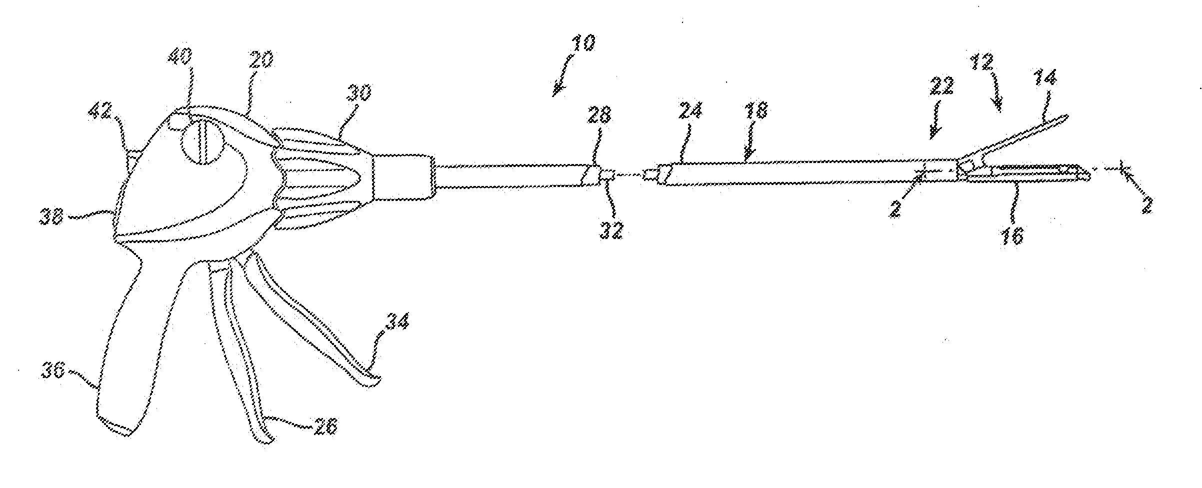
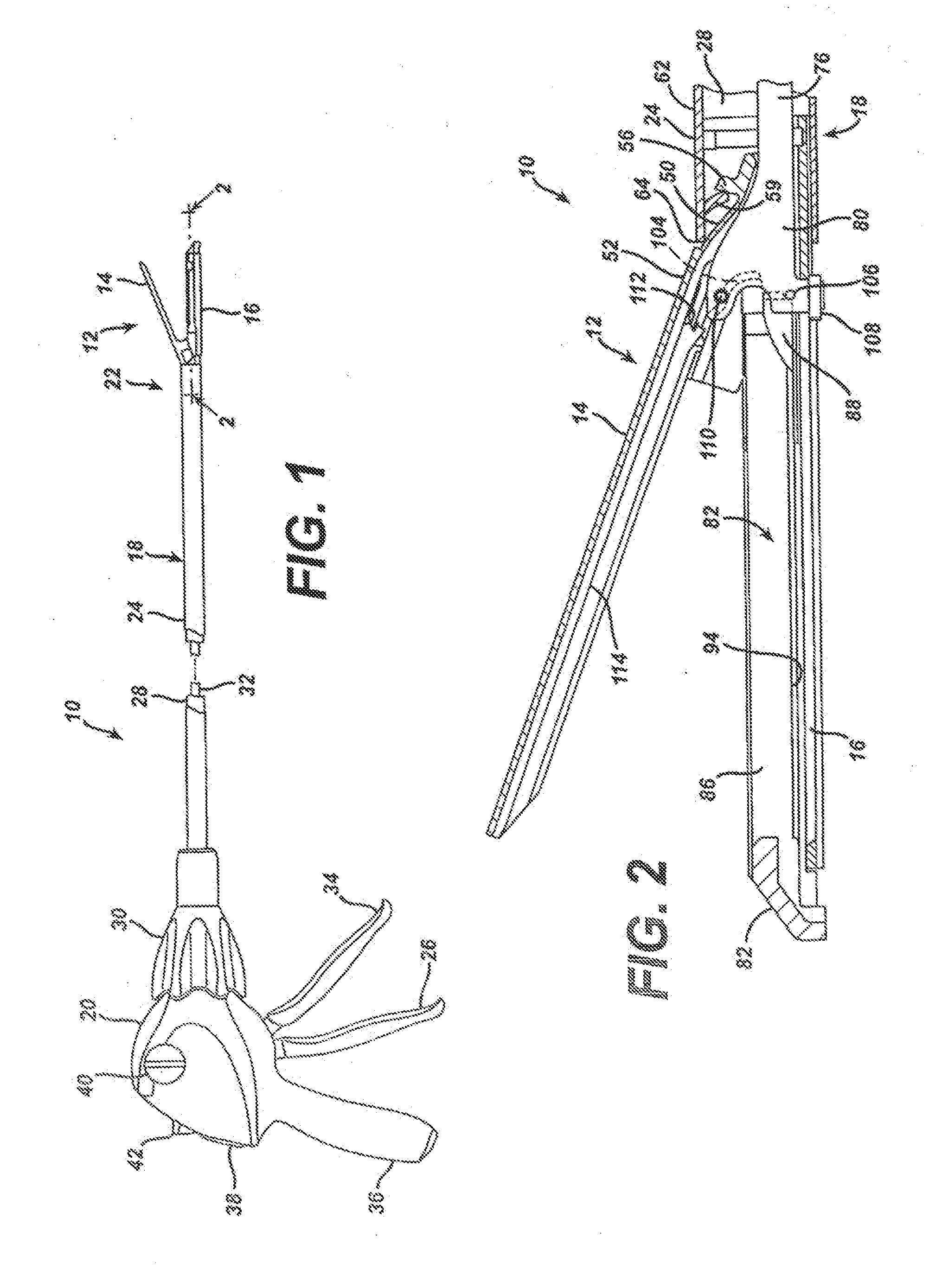
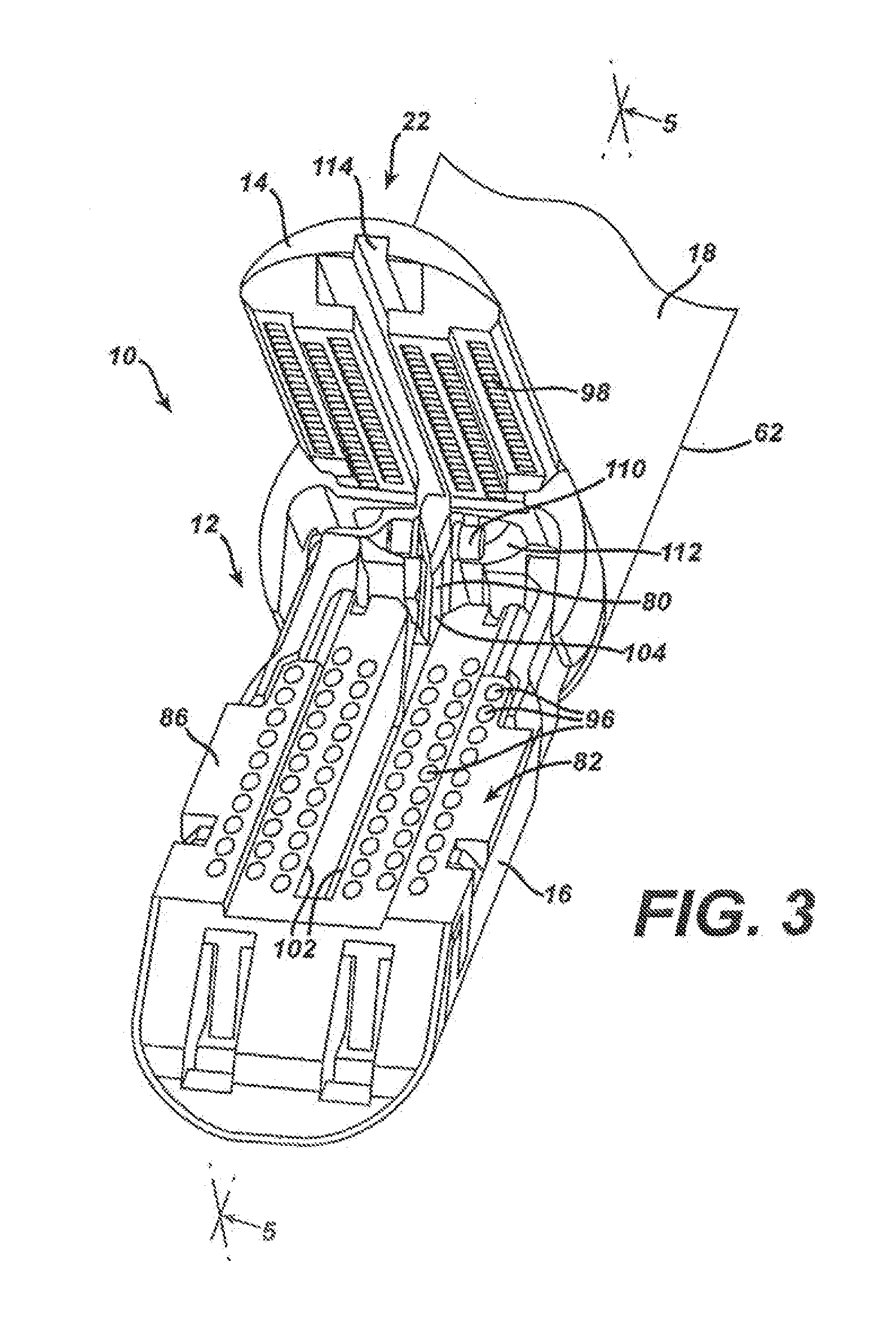
[0063]A surgical stapling and severing instrument, whether with a conventional solid or linked rack as advantageously depicted for a shorter handle, incorporates a multiple firing stroke capability allowing greater firing travel without an excessive amount of force required to squeeze a firing trigger. Between firing strokes, an anti-backup mechanism is incorporated so that a firing retraction bias does inadvertently cause firing retraction.

[0064]In FIGS. 1-30, a first version of the surgical stapling and severing instrument incorporates a side moving anti-backup release mechanism that causes automatic retraction at the end of firing travel. This version also includes a first version of a manual retraction assistance capability to overcome binding. In FIGS. 31-54, a second version of a surgical stapling and severing instrument mechanism includes two more anti-backup release mechanisms for automatic retraction at the end of firing travel. Further, the first version of the surgical st...


PUM


Abstract

A medical device for use in surgery made of a metal having a first hard coating layer applied to the metal, a second PTFE coating layer applied to the hard coating, and a third soap based lubricant coating layer applied to the PTFE layer.

Description

FIELD OF THE INVENTION[0001]The present invention relates in general to surgical stapler instruments that are capable of applying lines of staples to tissue while cutting the tissue between those staple lines and, more particularly, to improvements relating to stapler instruments and improvements in processes for forming various components of such stapler instruments that accomplish firing with multiple strokes of a trigger.BACKGROUND OF THE INVENTION[0002]Endoscopic surgical instruments are often preferred over traditional open surgical devices since a smaller incision tends to reduce the post-operative recovery time and complications. Consequently, significant development has gone into a range of endoscopic surgical instruments that are suitable for precise placement of a distal end effector at a desired surgical site through a cannula of a trocar. These distal end effectors engage the tissue in a number of ways to achieve a diagnostic or therapeutic effect (e.g., endocutter, gras...

Claims


Application Information

Patent Timeline
IPC IPC(8): A61B17/068
CPCA61B17/068A61B17/07207A61B17/2909A61B2017/00526A61B2017/00853A61B2017/07285A61B2017/2923A61B2017/2925C10M177/00C10M111/04C23C18/1254C10M2201/0623C10M2201/1053C10M2207/126C10M2209/0845C10M2213/0623C10M2229/025C23C18/1216C10N2050/023C10N2040/50C10N2010/02C10N2010/04
Inventor ONUKURI, SAMARDHANIM, JACQUELINE A.
Owner CILAG GMBH INTERNATIONAL
Why Eureka
Try Eureka