Compound cycle engine

a technology of compound cycle engine and cycle engine, which is applied in the direction of rotary or oscillating piston engine, rotary piston engine working fluid, etc., can solve the problems of limited performance, limited available power of compounded rotary engine, and known compounded rotary engine arrangemen

Active Publication Date: 2014-01-23
PRATT & WHITNEY CANADA CORP
View PDF10 Cites 70 Cited by
  • Summary
  • Abstract
  • Description
  • Claims
  • Application Information

AI Technical Summary

Problems solved by technology

However, known compounded rotary engine arrangements typically have limited available power for turbo compounding and / or limited performances, for example on start-up before the turbocharger is running.

Method used


Image

  • Compound cycle engine
  • Compound cycle engine
  • Compound cycle engine

Examples


Embodiment Construction

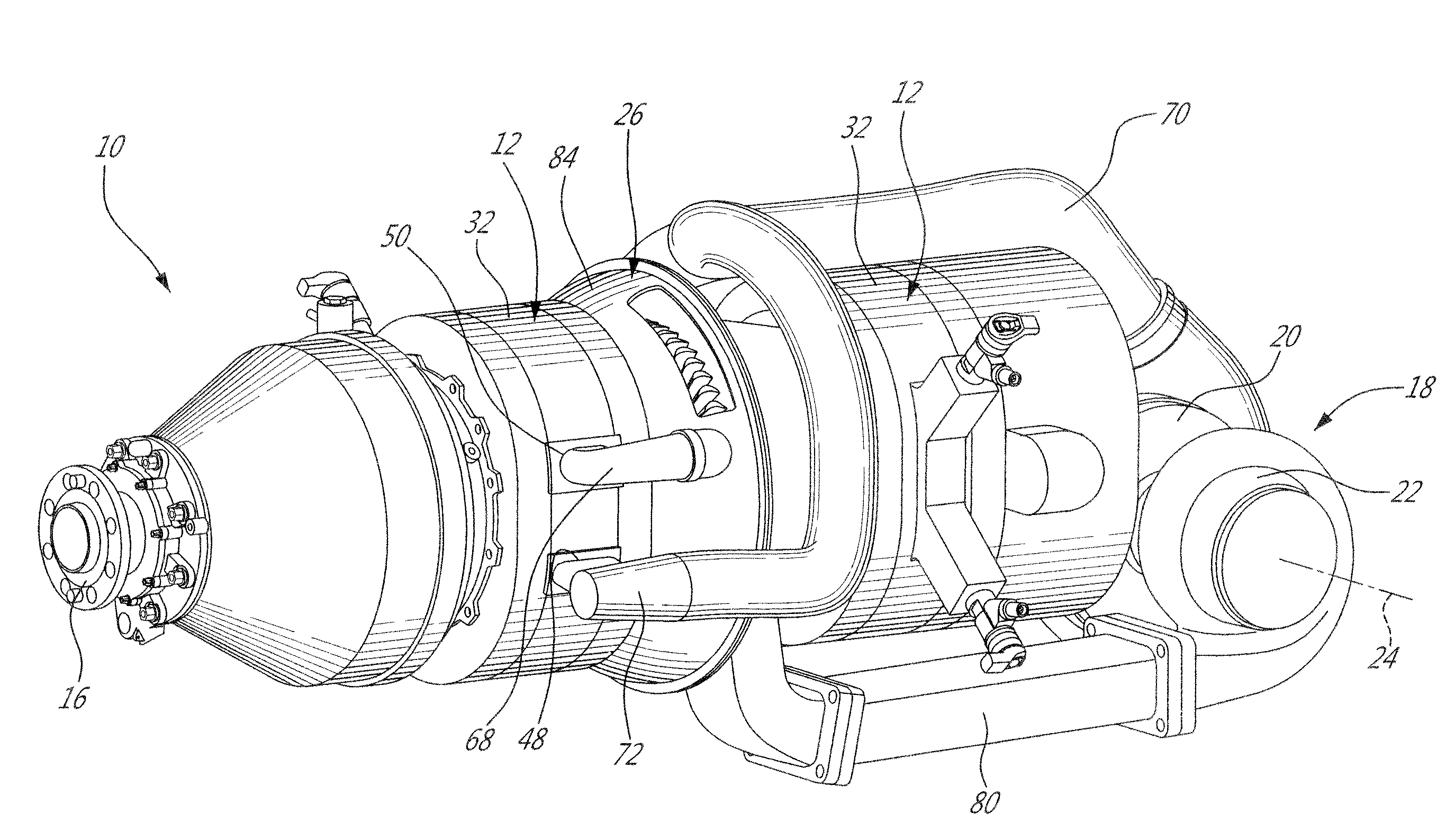
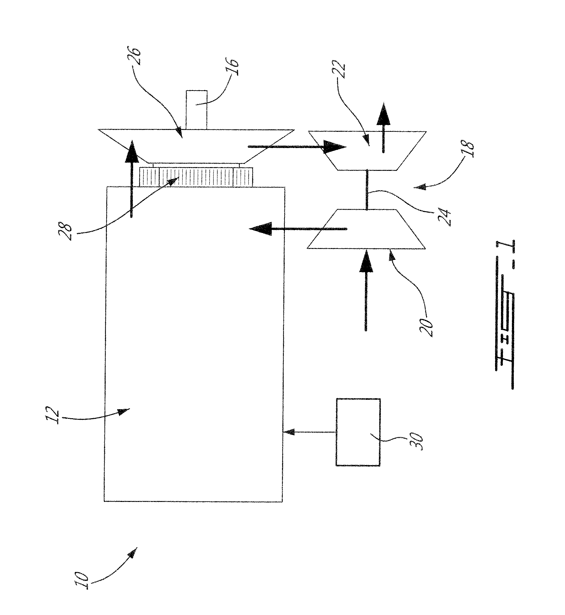
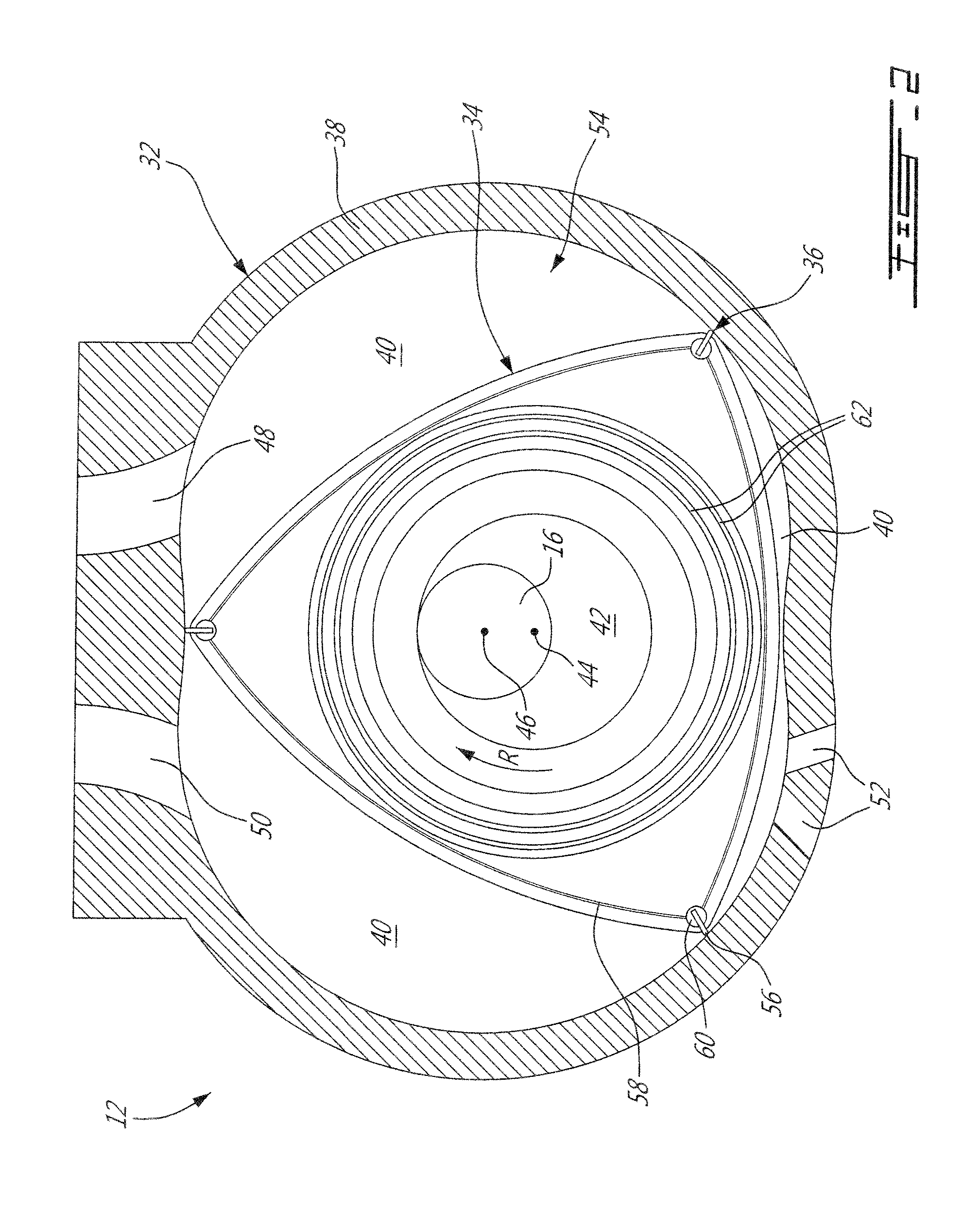
[0015]Referring now to FIG. 1, a compound cycle engine 10 is schematically shown. The compound cycle engine 10 includes rotary units 12, each unit 12 being defined by a rotary internal combustion engine having a rotor sealingly engaged in a respective housing. The rotary units 12 drive a common load. In the embodiment shown, the common load includes an output shaft 16 which may be for example connected to a propeller through a reduction gearbox (not shown) and to which the rotor of each unit 12 is engaged.

[0016]The compound cycle engine 10 also includes a turbocharger 18, formed by a compressor 20 and a pressure turbine 22 which are drivingly interconnected by a shaft 24. The compressor 20 and the turbine 22 may each be a single-stage device or a multiple-stage device with a single shaft or split on multiple independent shafts in parallel or in series, and may be a centrifugal or axial device. In the embodiment shown, the shaft 24 of the turbocharger 18 rotates independently of the ...


PUM


Abstract

A compound cycle engine having an output shaft; at least two rotary units each defining an internal combustion engine, a velocity turbine, and a turbocharger is discussed. The velocity turbine includes a rotor in driving engagement with the output shaft between two of the rotary units. The exhaust port of each rotary unit is in fluid communication with the flowpath of the velocity turbine upstream of its rotor. The outlet of the compressor of the turbocharger is in fluid communication with the inlet port of each rotary unit. The inlet of the pressure turbine of the turbocharger is in fluid communication with the flowpath of the velocity turbine downstream of its rotor. A method of compounding at least two rotary engines is also discussed.

Description

TECHNICAL FIELD[0001]The application relates generally to compound cycle engines and, more particularly, to such compound cycle engines including one or more rotary combustion engine(s).BACKGROUND OF THE ART[0002]Some compound cycle engines include a rotary engine turbocharged and compounded by a turbine located downstream of the turbocharger turbine. However, known compounded rotary engine arrangements typically have limited available power for turbo compounding and / or limited performances, for example on start-up before the turbocharger is running.SUMMARY[0003]In one aspect, there is provided a compound cycle engine comprising: an output shaft; at least two rotary units with each unit defining an internal combustion engine including a rotor sealingly and rotationally received within a respective housing, each housing defining an inlet port and an exhaust port, the rotor of each unit being mounted on the output shaft and in driving engagement therewith; a velocity turbine including...

Claims


Application Information

Patent Timeline
Patent Type & Authority Applications(United States)
IPC IPC(8): F02B37/00
CPCF01C1/22F01C11/002F01C11/008F02C6/12F02B37/005F02B53/02F02B53/10F02B55/14F02B2053/005Y02T10/12F02C5/00F02C6/00F02C7/36F05D2210/12F05D2220/32F05D2220/60
Inventor BOLDUC, SEBASTIENFONTAINE, MIKELANDRY, LUCTHOMASSIN, JEAN
Owner PRATT & WHITNEY CANADA CORP
Why Eureka
Try Eureka