Method for operating an internal combustion engine

a technology of internal combustion engine and combustion chamber, which is applied in the direction of machines/engines, electric control, instruments, etc., can solve the problems of unfavorable spray preparation and therefore combustion, formation of deposits in the combustion chamber, and low torque of the corresponding cylinder, so as to reduce the nox emission and reduce the combustion temperature. , the effect of simple means

Inactive Publication Date: 2005-05-17
ROBERT BOSCH GMBH
View PDF14 Cites 101 Cited by
  • Summary
  • Abstract
  • Description
  • Claims
  • Application Information

AI Technical Summary

Benefits of technology

[0007]The especially great advantage of the present invention is that the combustion chamber can be kept free of deposits with simple means over the entire service life of the engine, whereby always optimal conditions are given for a good combustion.
[0008]A further advantage of the invention is that the combustion temperature is reduced with the injection of water and, associated therewith, the NOx emission becomes lower. Furthermore, the thermodynamic efficiency of the engine is improved because of the water vapor pressure of the water vaporized in the combustion chamber at high temperature.

Problems solved by technology

The operation of internal combustion engines in the presence of unfavorable operating conditions can lead to the formation of deposits in the combustion chamber.
These deposits can operate unfavorably on the spray preparation and therefore on the combustion.
A coking of injection valves can cause a torque of the corresponding cylinder which is too low especially in an engine having direct injection.
In this case, the corresponding cylinder runs too lean.
Here, an increased rough running can occur caused by a low tolerance compatibility of the combustion process in stratified operation and / or because of tolerances of the high pressure injection valves which are used or in the distribution of the fuel to the individual cylinders.
Also, deterioration-caused changes of the throughflow characteristics of the high pressure injection valves can have an effect.

Method used


Image

  • Method for operating an internal combustion engine
  • Method for operating an internal combustion engine
  • Method for operating an internal combustion engine

Examples


Embodiment Construction

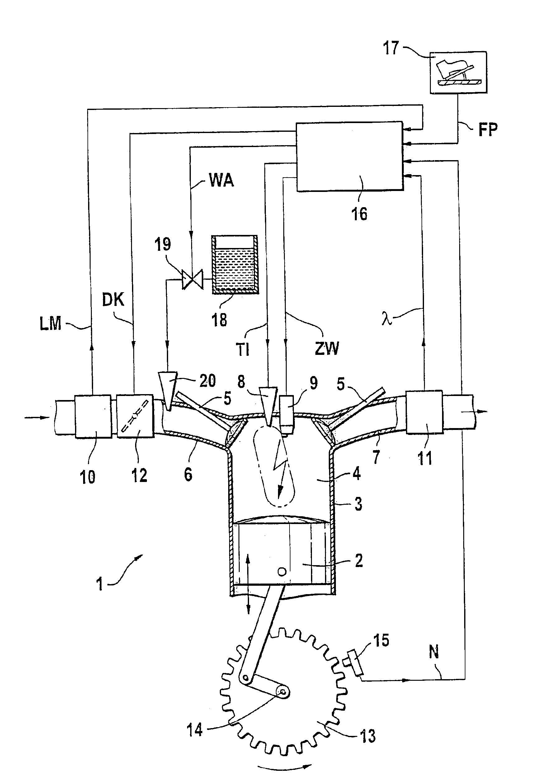
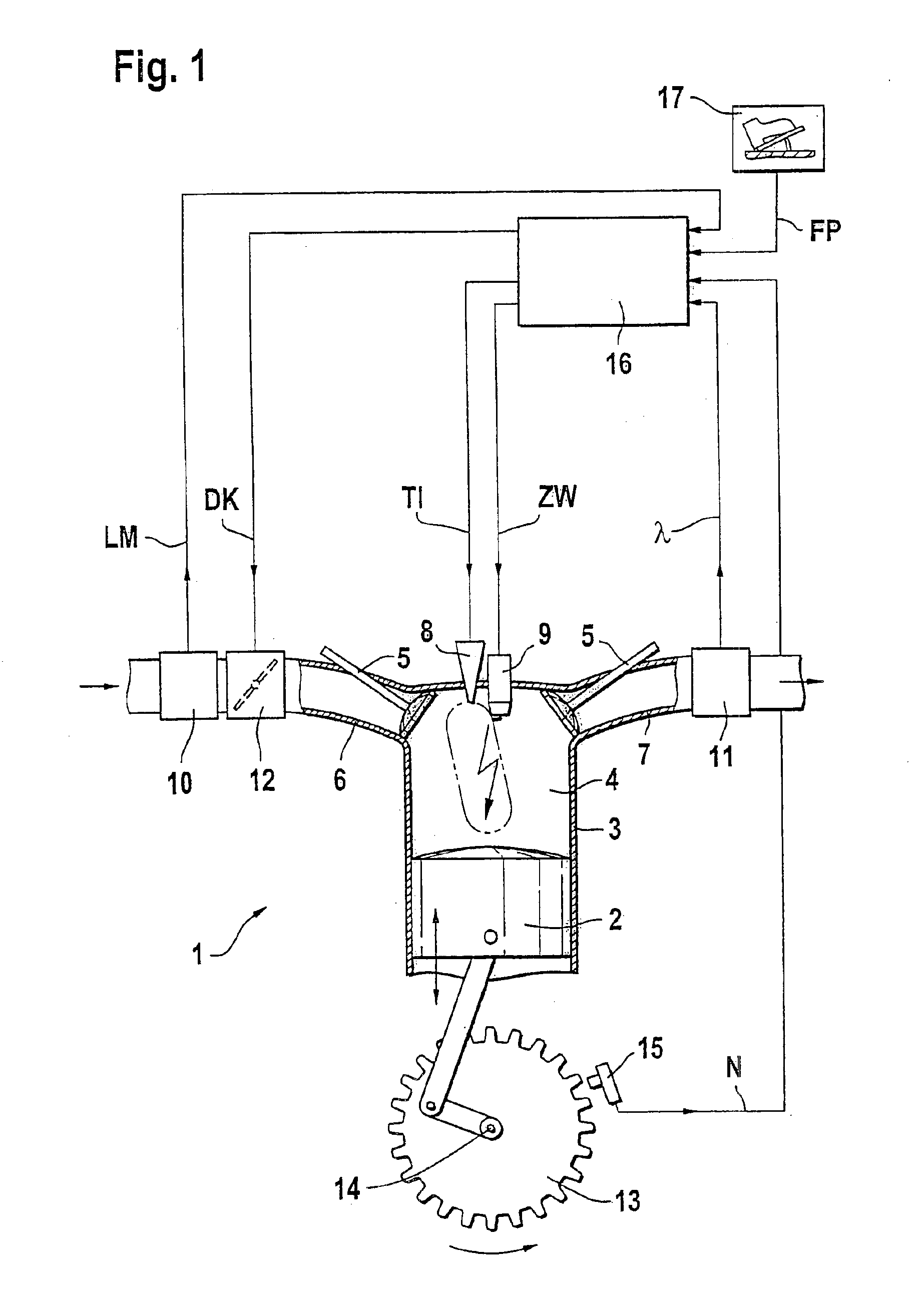
[0013]FIG. 1, an internal combustion engine 1 is shown wherein a piston 2 is movable back and forth in a cylinder 3. The cylinder 3 is provided with a combustion chamber 4 to which an intake manifold 6 and an exhaust-gas pipe 7 are connected via valves 5. Furthermore, an injection valve 8 and a spark plug 9 are associated with the combustion chamber 4. The injection valve 8 is driven by a signal TI and the spark plug 9 is driven by a signal ZW. The signals TI and ZW are transmitted by a control apparatus 16 to the injection valve 8 and the spark plug 9, respectively.

[0014]The intake manifold 6 is provided with an air mass sensor 10 and the exhaust-gas pipe 7 is provided with a lambda sensor 11. The air mass sensor 10 measures the air mass of the fresh air supplied to the intake manifold 6 and generates a signal LM in dependence thereon. The lambda sensor 11 measures the oxygen content of the exhaust gas in the exhaust-gas pipe 7 and generates a signal lambda in dependence thereon. T...


PUM


Abstract

The operation of an internal combustion engine under unfavorable operating conditions can lead to the formation of deposits in the combustion chamber (4). A method and an arrangement for operating an internal combustion engine (1), especially of a motor vehicle, is suggested, wherein fuel is conducted into a combustion chamber (4) and is there combusted. When deposits are detected in the combustion chamber (4), measures are initiated in a targeted manner for cleansing the combustion chamber (4). A knocking combustion is especially introduced and/or a cleansing liquid is added to the inducted combustion air.

Description

FIELD OF THE INVENTION[0001]The invention relates to a method and an arrangement for operating an internal combustion engine, especially of a motor vehicle, wherein fuel is directed into the combustion chamber and there combusted.BACKGROUND OF THE INVENTION[0002]The operation of internal combustion engines in the presence of unfavorable operating conditions can lead to the formation of deposits in the combustion chamber. Especially for engines having direct fuel injection, deposits can form, for example, on the injection valves, that is, on the tips or in the tips of the injection valves. These deposits can operate unfavorably on the spray preparation and therefore on the combustion. As a rule, one speaks of a coking of the injection valves.[0003]An electronic control arrangement is known from DE 198 28 279 A1 by means of which an equalization of the cylinder-individual torque contributions can be carried out in a multi-cylinder engine. Here, to balance the cylinder-individual torqu...

Claims


Application Information

Patent Timeline
Patent Type & Authority Patents(United States)
IPC IPC(8): F02M65/00F02D37/00F02D41/14F02D41/22F02D41/00F02D37/02F02B77/04F02D41/30F02D41/34F02B75/12F02B75/00F02D45/00
CPCF02B77/04F02D35/027F02D37/02F02D41/0025F02D41/0085F02D41/1498F02D41/221F02D41/3076F02M65/007Y02T10/123F02D41/187F02D41/3029F02D2041/389F02D2200/1015F02B2075/125Y02T10/12
Inventor UHL, STEPHANROTH, ANDREAS
Owner ROBERT BOSCH GMBH
Why Eureka
Try Eureka