System and method for controlling a vehicle

a vehicle and system technology, applied in the field of vehicles, can solve the problem that the level of tractive effort of the vehicle is sufficient to overcome the braking for

Active Publication Date: 2014-01-30
GE GLOBAL SOURCING LLC
View PDF1 Cites 35 Cited by
  • Summary
  • Abstract
  • Description
  • Claims
  • Application Information

AI Technical Summary

Problems solved by technology

Concurrently, a level of tractive effort of the vehicle is applied sufficient to overcome the braking force.

Method used


Image

  • System and method for controlling a vehicle
  • System and method for controlling a vehicle
  • System and method for controlling a vehicle

Examples


Embodiment Construction

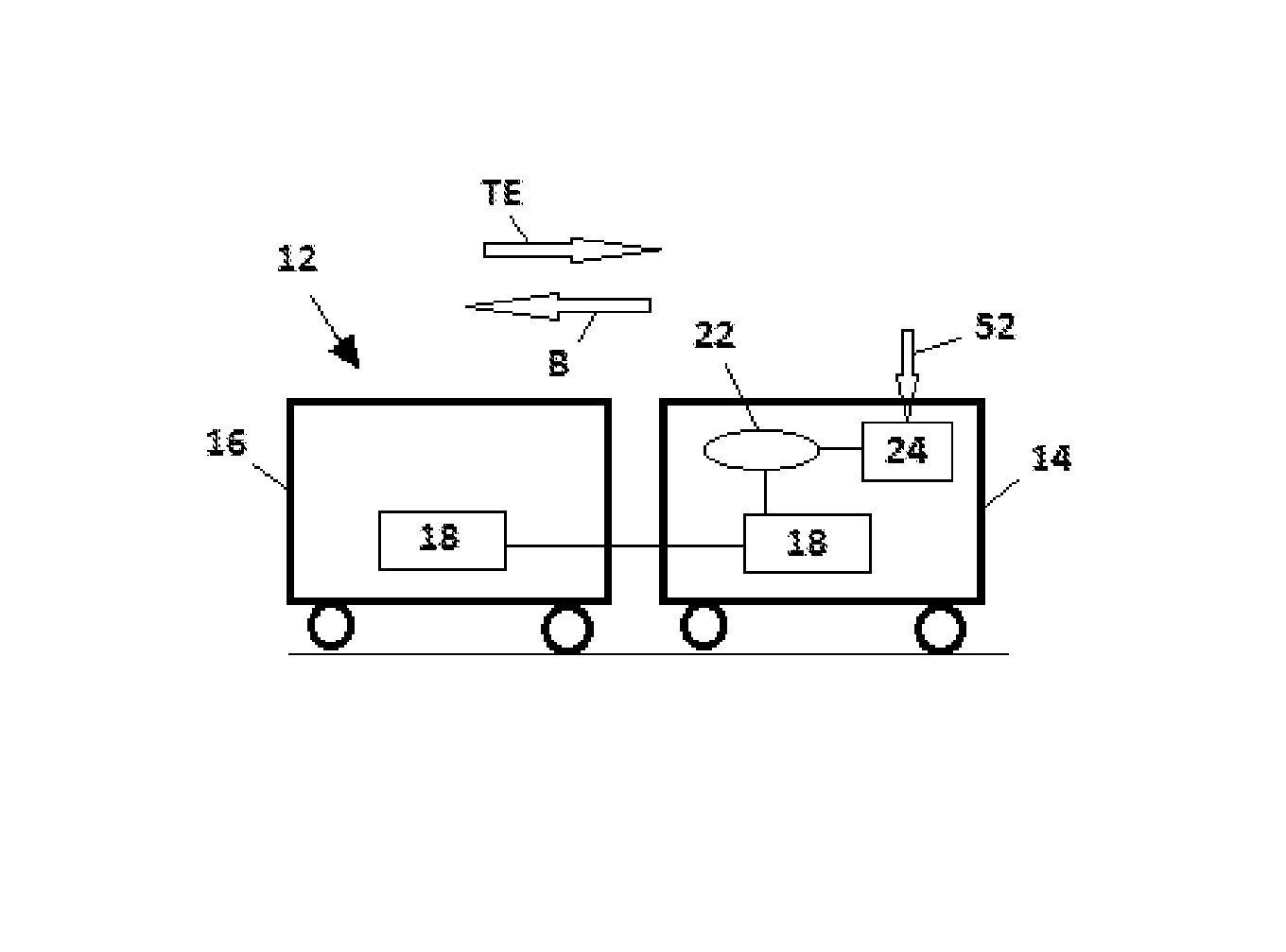
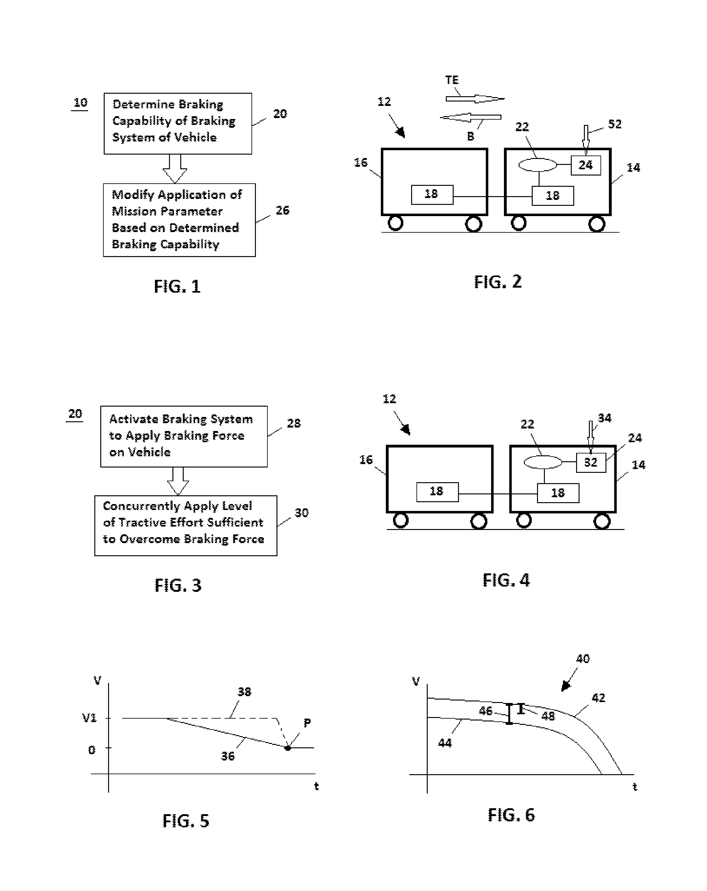
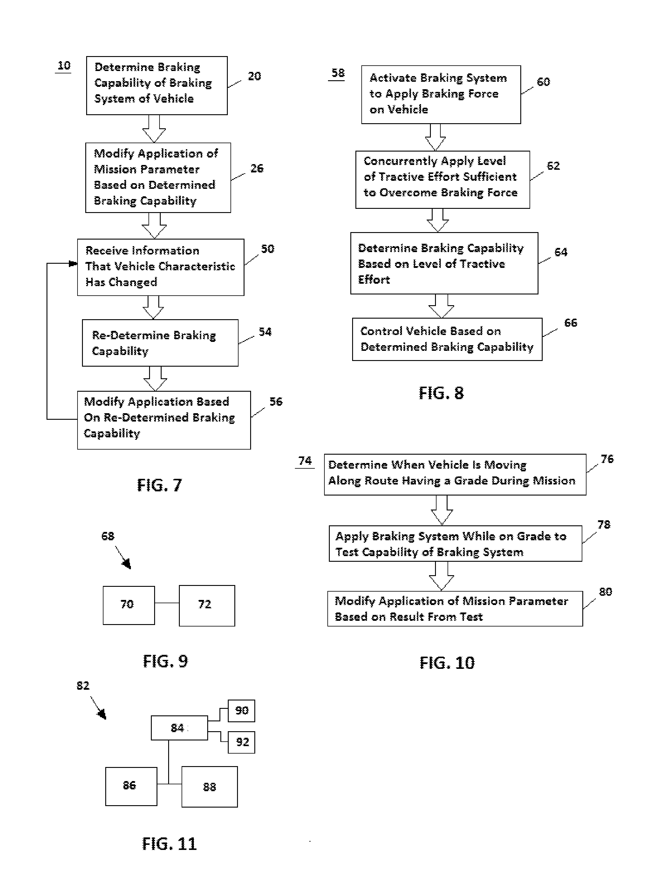
[0026]Reference will be made below in detail to exemplary embodiments of the invention, examples of which are illustrated in the accompanying drawings. Wherever possible, the same reference numerals used throughout the drawings refer to the same or like parts; however, the existence of the same or like parts in multiple embodiments does not mean every embodiment of the invention necessarily includes such parts. Exemplary embodiments of the invention solve problems in the art by controlling a vehicle based on a determined condition of a braking system of the vehicle. Additionally, embodiments of the invention can be implemented in numerous ways, including as a system (including a computer processing system), a method (including a computerized method), an apparatus, a computer readable medium, a computer program product, or a data structure tangibly fixed in a computer readable memory. Several embodiments of the invention are discussed below.

[0027]Although embodiments are described he...


PUM


Abstract

A method for vehicle control comprises determining a braking capability of a braking system of a rail vehicle or other vehicle, and modifying application of at least one mission parameter by a control system of the vehicle based on the determined braking capability. Braking capability may be determined by activating the braking system of the vehicle to apply a braking force on the vehicle, and concurrently, applying a level of tractive effort of the vehicle is sufficient to overcome the braking force. The braking capability is determined based on the level of tractive effort.

Description

BACKGROUND OF THE INVENTION[0001]1. Field[0002]Embodiments of the invention relate to vehicles, e.g., rail vehicles. Other embodiments relate to methods and systems for controlling rail vehicles or other vehicles.[0003]2. Discussion of Art[0004]Especially when various on-board systems are integrated with a vehicle braking system for conjointly operating the vehicle, the vehicle may be operated according to a “worst case” assumption of braking capability. For example, in the case of a locomotive or other rail vehicle, the rail vehicle may be operated according to the assumption that only fifty percent of mechanical braking capability (e.g., air brakes) is available and with no dynamic brake capability. Making such assumptions may result in the rail vehicle being slowed earlier than necessary, which results in a loss of average speed over a full duration of a trip / mission. Additionally, this may result in delay and loss of route capacity, considering that other vehicles also operate o...

Claims


Application Information

Patent Timeline
Patent Type & Authority Applications(United States)
IPC IPC(8): B60W40/105
CPCB60W40/105
Inventor KUMAR, AJITH KUTTANNAIRSMITH, EUGENE A.HOUPT, PAUL KENNETHSHAFFER, GLENN ROBERTNOFFSINGER, JOSEPH FORRESTMCMANUS, BRIAN J.COOPER, JAREDPELTZ, DAVID MICHAEL
Owner GE GLOBAL SOURCING LLC
Why Eureka
Try Eureka