Multi-Directional Tilt Switch

a multi-directional, tilting technology, applied in the direction of electric switches, basic electric elements, electric apparatus, etc., can solve the problem that the requirement of waterproof cannot be m

Inactive Publication Date: 2014-02-06
CHOU
View PDF2 Cites 19 Cited by
  • Summary
  • Abstract
  • Description
  • Claims
  • Application Information

AI Technical Summary

Problems solved by technology

Relatively speaking, the waterproof requirement cannot also be met.

Method used


Image

  • Multi-Directional Tilt Switch
  • Multi-Directional Tilt Switch
  • Multi-Directional Tilt Switch

Examples


Embodiment Construction

[0020]The above-mentioned and other technical contents, features, and effects of this invention will be clearly presented from the following detailed description of one embodiment in coordination with the reference drawings.

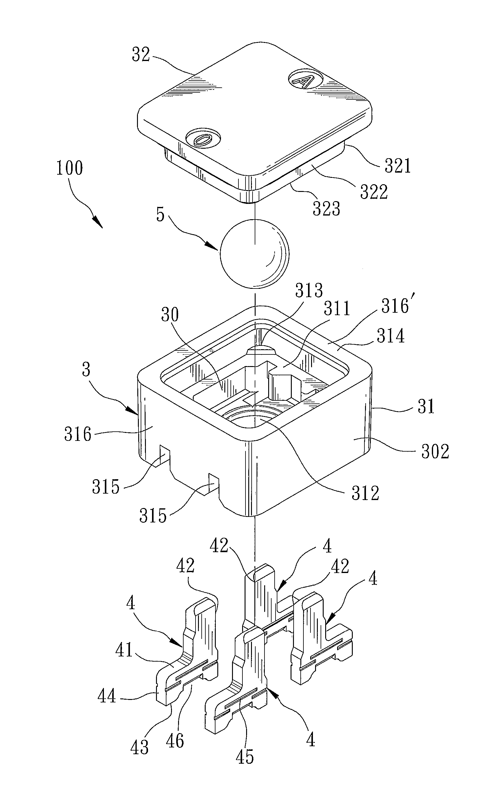
[0021]Referring to FIGS. 3, 4 and 5, the preferred embodiment of a multi-directional tilt switch 100 according to this invention is shown to comprise a housing 3, four spaced-apart conductive terminals 4, and a conductive body 5.

[0022]The housing 3 has a housing inner surface defining a chamber 30, a housing outer surface opposite to the housing inner surface, and a plurality of slots 315 extending through the housing inner and outer surfaces. Preferably, the housing 3 includes a base 31 and a cover 32 that are bonded to each other to define the chamber 30. The base 31 includes a base wall 301 opposite to the cover 32, and a surrounding wall 302 extending transversely from the base wall 301 to the cover 32. The base wall 301 has an indentation 312 formed in an in...


PUM


Abstract

A multi-directional tilt switch includes a housing inner surface defining a chamber, a housing outer surface opposite to the housing inner surface, a plurality of slots extending through the housing inner and outer surfaces, and a plurality of conductive terminals each including an insert portion inserted in a corresponding slot, a contact portion extending into the chamber, and a first connecting surface exposed from the housing outer surface. A conductive body is accommodated movably in the chamber between a first position, where the conductive body bridges two contact portions, and a second position, where the conductive body does not bridge any two contact portions.

Description

1. FIELD OF THE INVENTION[0001]The invention relates to a tilt switch, more particularly to a multi-directional tilt switch that uses angular changes to effect ON / OFF switching.2. DESCRIPTION OF THE RELATED ART[0002]Referring to FIG. 1, a rolling-ball switch 1, as disclosed in Taiwanese Patent No. 1310951, mainly comprises a housing 11 defining a chamber 10, two conductive terminals 12, 13, and a conductive ball 14 disposed in the chamber 10. Each of the conductive terminals 12, 13 has a plate shape, and includes two contact portions 121, 131 extending into the chamber 10, and an elongated connecting portion 122, 132 exposed from the housing 11. The contact portions 121, 131 are disposed in pairs around the conductive ball 14. Through such a configuration, when the rolling-ball switch 1 produces an angular change due to vibration, and the conductive ball 14 contacts simultaneously one of the contact portions 121 and one of the contact portions 131, the circuit of the switch 1 is clo...

Claims


Application Information

Patent Timeline
Patent Type & Authority Applications(United States)
IPC IPC(8): H01H35/02
CPCH01H35/02H01H9/04H01H11/00
Inventor CHOU, TIEN-MING
Owner CHOU
Why Eureka
Try Eureka