Microscope

a microscope and microscope technology, applied in the field of microscopes, can solve the problems of serious defects which are not acceptable to users, three-dimensional impressions vary with magnification, and the requirement is difficult to meet in practice, so as to achieve the effect of effectively avoiding getting in the way of the main operator and effectively avoiding vignetting

Inactive Publication Date: 2006-06-06
LEICA INSTR SINGAPORE PTE
View PDF14 Cites 8 Cited by
  • Summary
  • Abstract
  • Description
  • Claims
  • Application Information

AI Technical Summary

Benefits of technology

[0009]The microscope according to the invention also ensures that both the main operator and an assistant are provided with a stereoscopic image impression irrespective of the magnification set, the field of viewing being substantially the same for the main operator and the assistant. It has also proved advantageous that the microscope according to the invention uses only one main objective, as the splitting of the optical paths into the main operator's optical paths and the assistant's optical paths only takes place after the optical paths have passed through the main objective.
[0011]According to a particularly preferred embodiment of the microscope according to the invention, a magnification system for the first observer (main operator) is arranged in the second or middle plane of the microscope and a magnification system for the second observer (assistant) is arranged in the third (uppermost) plane of the microscope. This measure of arranging the magnification systems for the first and second observers in the second and third planes extending substantially horizontally, in particular, means that the overall height of the microscope as a whole can be kept to a minimum. Because different magnification systems are provided for the first and second observers, different magnifications can be set for the first observer (main operator) and second observer (assistant) as necessary. It should be mentioned that the horizontal extent of the planes of the microscope, particularly when the microscope according to the invention is used in the field of neurosurgery, is only a preferred orientation. In theory, the microscope according to the invention should be able to be oriented so that the planes extend diagonally in space, preferably parallel to one another.
[0012]Expediently, at least one of the magnification systems for the first or second observer has a zoom lens or zoom system. With a zoom lens of this kind it is possible to achieve the desired magnification tailored to individual requirements over a given zoom range.
[0013]According to another preferred embodiment of the microscope according to the invention the optical viewing paths are pivotable in the second plane and / or the third plane. This measure means, for example, that the assistant's microscope can be freely used in all directions in space, thus effectively avoiding getting in the way of the main operator.
[0014]Conveniently, at least one of the deflecting devices by means of which the optical viewing paths can be deflected from one of the planes into another plane is semi-transparent. This allows the assistant's optical paths to be uncoupled without restricting the optical path pupils (physical beam splitting). In this way vignetting can be effectively avoided.
[0015]According to another preferred embodiment of the microscope according to the invention, the magnification systems for the first and second observer are mechanically and / or electrically coupled to one another. This ensures that, particularly when using zoom systems as the magnification system, the same magnifications can be achieved for both observers or the magnifications selected can be varied synchronously with one another.

Problems solved by technology

This requirement is difficult to meet in practice as the microscope has to be able to be oriented in all directions in space and must be capable of being operated in all these orientations.
This makes the development of such a microscope easier on the one hand but gives rise to serious defects which are not acceptable to the users in certain fields of application.
One such defect is for example the fact that the three dimensional impression varies with the magnification.
A disadvantage of this is that the free working interval underneath the microscope (i.e. the distance between the microscope and the object which is to be observed) is reduced and the overall height of the microscope as a whole is increased.
As a separate main objective is also required for the assistant microscope, this microscope also proves to be relatively complicated in the provision of the respective optical components.

Method used


Image

  • Microscope
  • Microscope

Examples


Embodiment Construction

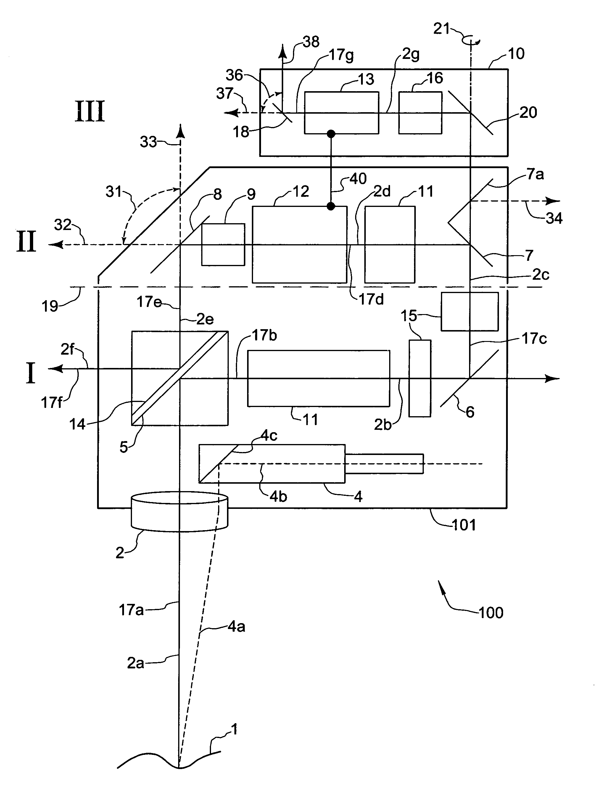
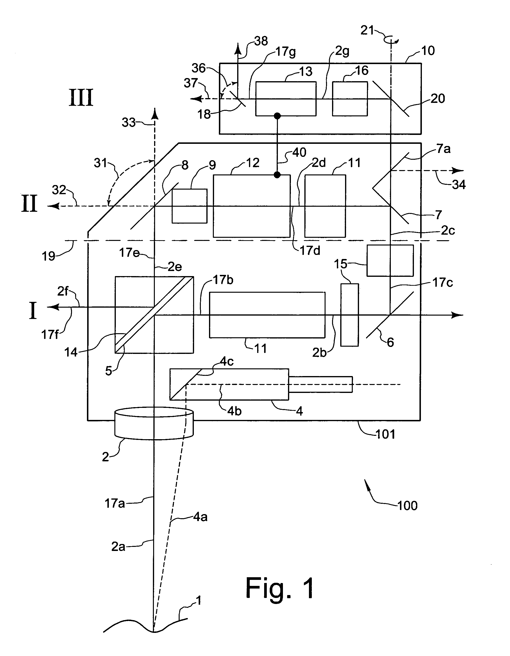
[0018]A preferred embodiment of a microscope according to the invention in the form of a stereomicroscope is generally designated 100 in FIG. 1. The microscope 100 is intended to be used to observe, for example, a neurological object 1. An illuminating device which illuminates the object 1 along an illumination axis 4a is generally designated 4. Microscope 100 generally comprises a main microscope portion 101 and an assistant microscope portion 10.

[0019]The object 1 is imaged into the microscope 100 through a main objective 2. The optical axis of the main objective 2 is designated 2a. In the embodiment shown it runs substantially vertically, while it should be pointed out that the microscope 100 and hence the optical axis 2a as well is capable of being oriented in every direction in space. Passing through the main objective 2 is an optical viewing path 17a which runs along the optical axis 2a. The optical viewing path 17a is then deflected by a deflecting element 5 into a first plan...


PUM


Abstract

Microscope, particularly a stereomicroscope, for simultaneous observation of an object by a first and a second observer, comprising a main objective (2) having an optical axis (2a); an optical viewing path; a plurality of deflector elements (5, 6, 7) for deflecting the optical viewing path into a first plane I extending at an angle to the optical axis of the main objective and subsequently into a second plane II substantially parallel to and above the first plane I; an uncoupling device (7) in the optical viewing path for uncoupling an optical viewing path of the second observer from an optical viewing path of the first observer; and a deflector element (20) for deflecting the optical viewing path of the second observer into a third plane III which extends substantially parallel to the first and second planes I, II, wherein the second plane II is located between the first plane I and the third plane III.

Description

CROSS REFERENCE TO RELATED APPLICATIONS[0001]The present application claims priority of German patent application number 103 25 575.3 filed Jun. 5, 2003, which is incorporated herein by reference.FIELD OF THE INVENTION[0002]The present invention relates to microscopes, particularly stereomicroscopes, for simultaneous observation of an object by a first observer and a second observer.BACKGROUND OF THE INVENTION[0003]New operating techniques in modern day neurosurgery require both a main operator and an assistant to view the same operating area at the same time. The main operator and assistant should be able to view the same field of vision. This requirement is difficult to meet in practice as the microscope has to be able to be oriented in all directions in space and must be capable of being operated in all these orientations.[0004]The Japanese manufacturer Olympus has developed a microscope which can be used in neurosurgery in which the solution is essentially based on the use of a ...

Claims


Application Information

Patent Timeline
Patent Type & Authority Patents(United States)
IPC IPC(8): G02B21/00G02B21/18A61B19/00G02B21/22
CPCG02B21/22G02B21/18A61B19/5223A61B90/20
Inventor SANDER, ULRICH
Owner LEICA INSTR SINGAPORE PTE
Why Eureka
Try Eureka