Magnetic auxiliary mechanism for pivoted tool

a technology of auxiliary mechanism and tool, which is applied in the field of pivoted hand tools, can solve the problems of less effective in facilitating energy saving, prone to elastic fatigue of compression springs, and defects in conventional approaches, and achieves the effects of convenient operation, simple overall appearance, and safe storag

Inactive Publication Date: 2014-02-13
LIQUIMIND
View PDF4 Cites 17 Cited by
  • Summary
  • Abstract
  • Description
  • Claims
  • Application Information

AI Technical Summary

Benefits of technology

[0010]With the inventive configuration, the disclosed magnetic auxiliary mechanism provides sim...

Problems solved by technology

However, the conventional approach has its defects.
First, after long-term use, the compression spring tends to have elastic fatigue, and become less effective in facilitating saving energy.
In addition, the spring bridging between the two handles...

Method used


Image

  • Magnetic auxiliary mechanism for pivoted tool
  • Magnetic auxiliary mechanism for pivoted tool
  • Magnetic auxiliary mechanism for pivoted tool

Examples


Embodiment Construction

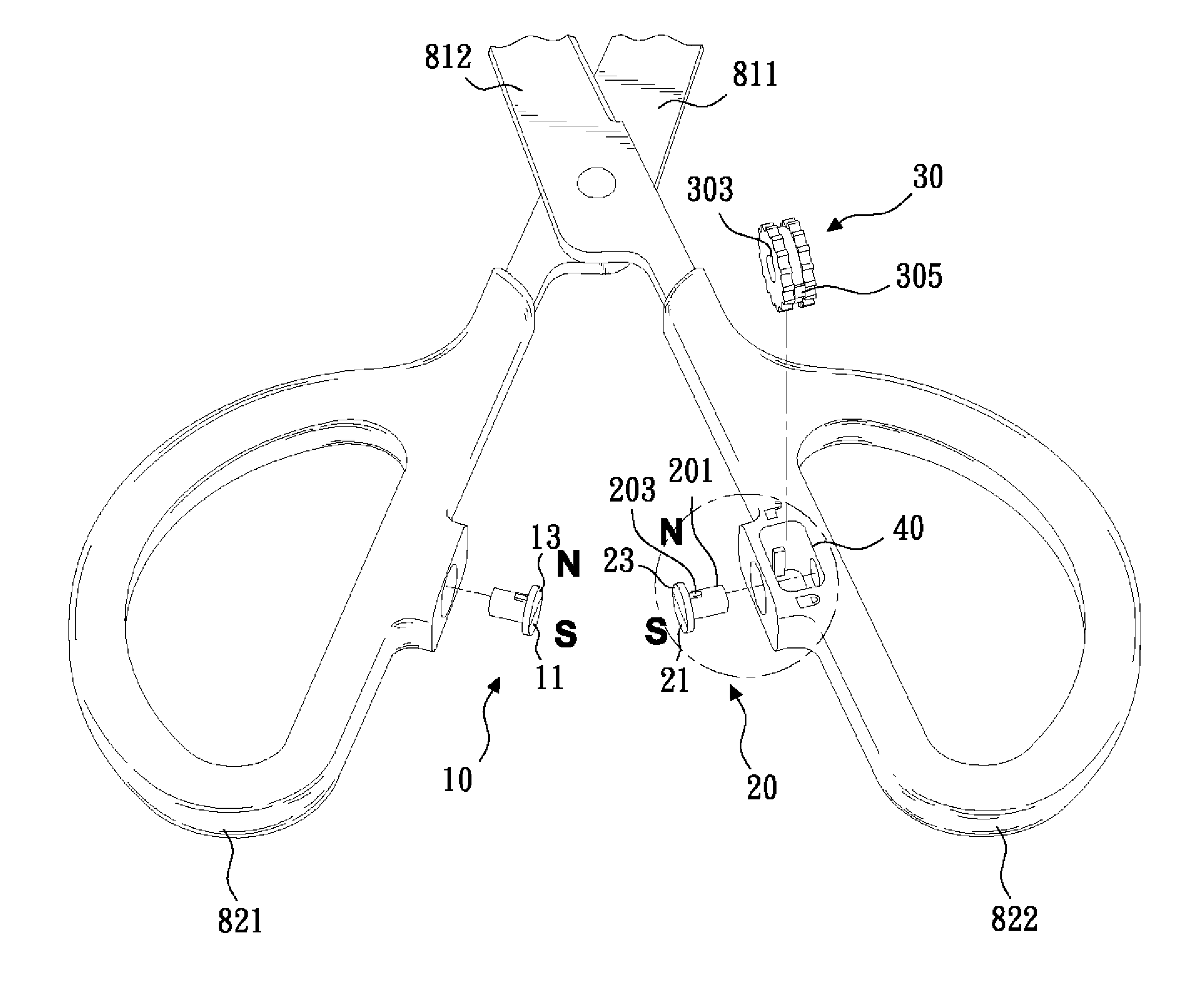
[0020]According to the present invention, a magnetic auxiliary mechanism is designed for a pivoted tool. It is well known that a pivoted tool typically has paired handles to be drawn together or separated apart to thereby close or open a pair of functional jaws. Examples of such pivoted tools include, but are not limited to, scissors, shears and pliers. The magnetic auxiliary mechanism of the present invention is configured to be installed between the paired handles.

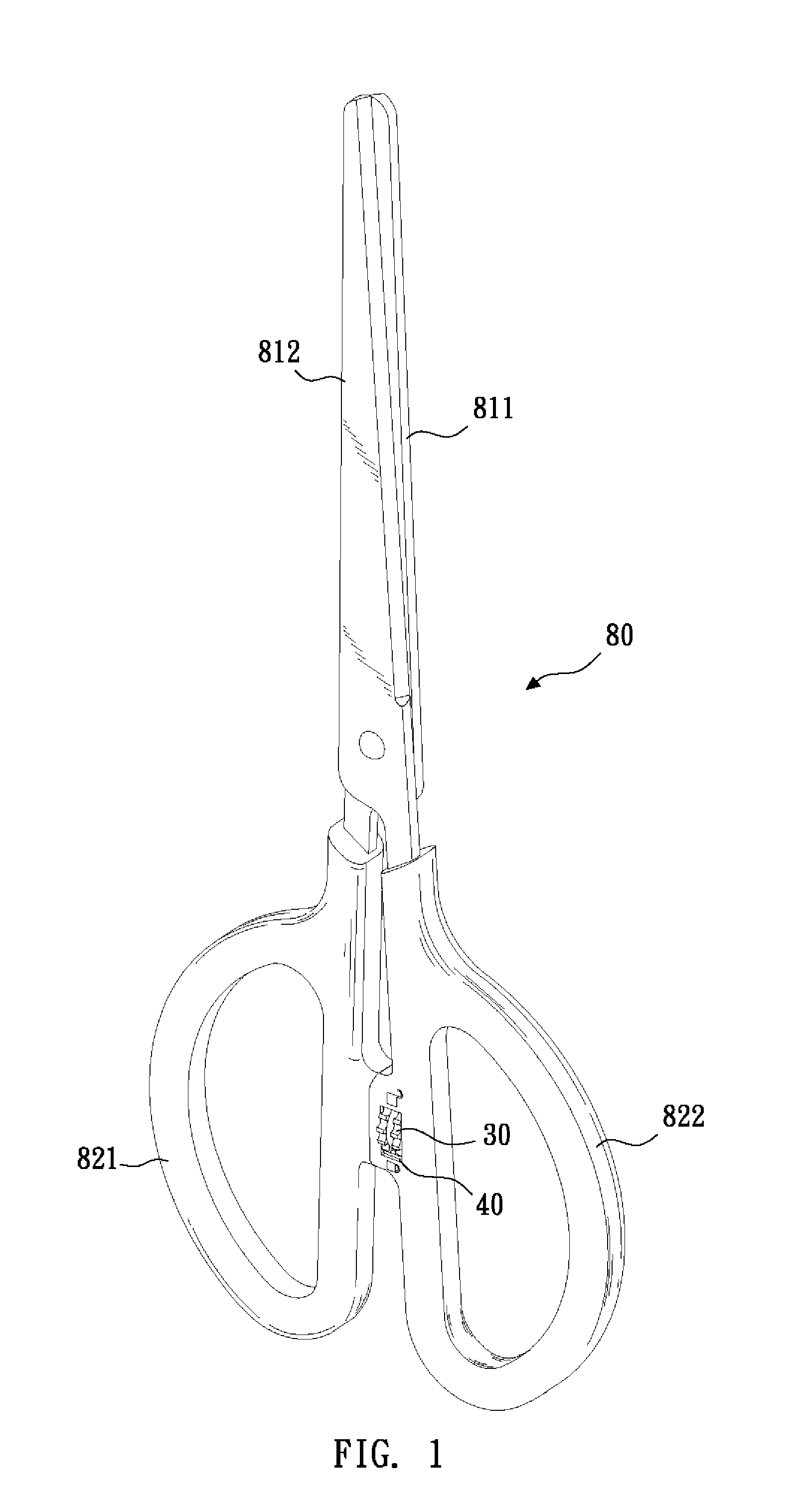
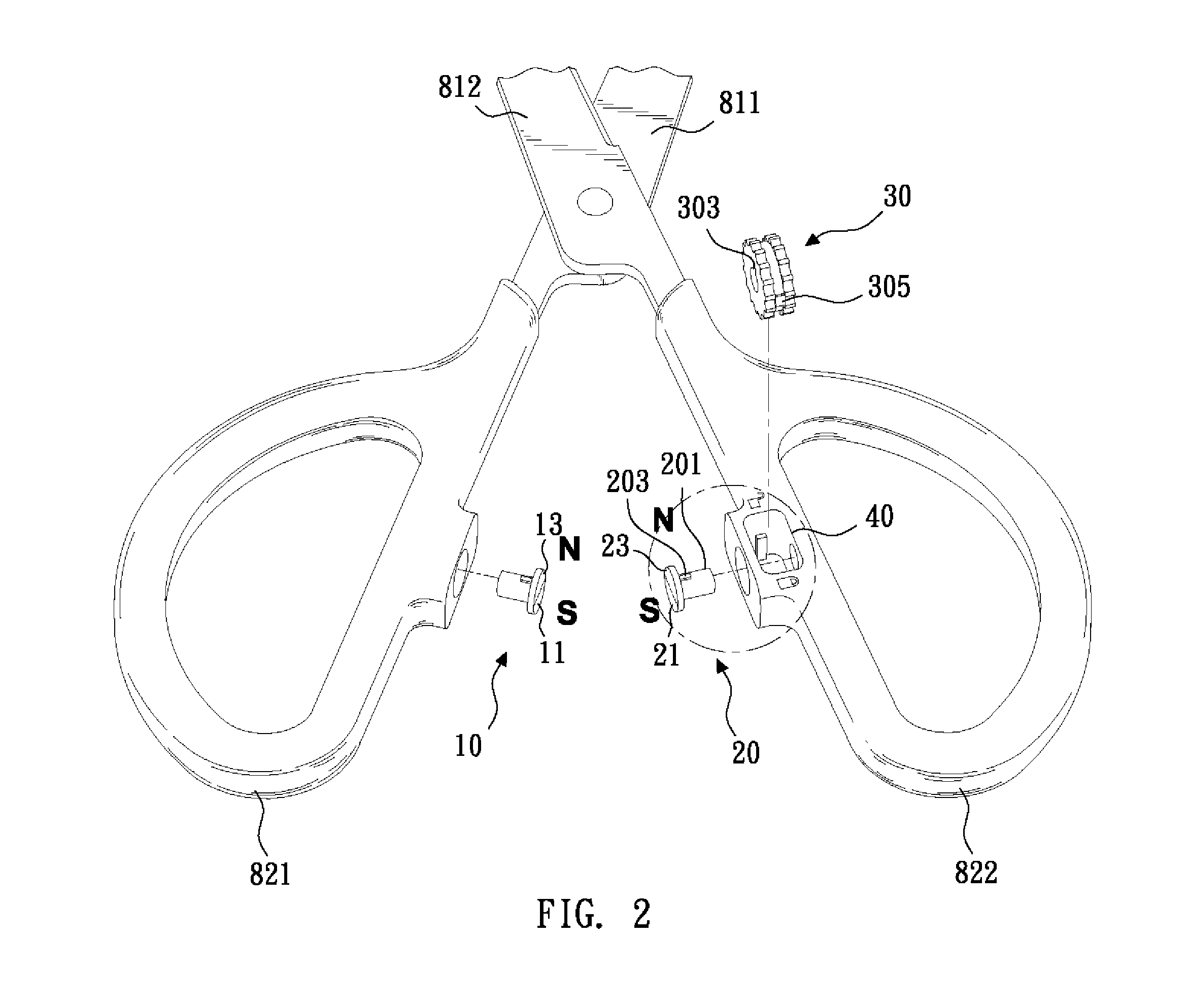
[0021]For illustrating the concept of the present invention, some preferred embodiments are provided and described herein. Please first refer to FIG. 1, FIG. 2 and FIG. 2a for a perspective view of a pair of scissors having the disclosed magnetic auxiliary mechanism and exploded views of the magnetic auxiliary mechanism from the scissors.

[0022]In the depicted embodiment, the scissors 80 has a pair of blades 811 and 812. When handles 821 and 822 of the scissors 80 are drawn together, the blades 811 and 812 approach each o...


PUM


Abstract

A magnetic auxiliary mechanism for a pivoted tool is disclosed. When an adjustable magnetic member therein is set in a released state, a repelling force generated between the adjustable member and a fixed magnetic member helps to push handles of the pivoted tool to move in opposite directions, thereby facilitating operation. When the adjustable magnetic member is set in a locked state, an attracting force generated between the adjustable and fixed magnetic members helps to hold the handles of the pivoted tool together. The magnetic auxiliary mechanism provides simple overall appearance, convenient operation and safe storage to the pivoted tool.

Description

BACKGROUND OF THE INVENTION[0001]1. Technical Field[0002]The present invention relates to pivoted hand tools, and more particularly, to a magnetic auxiliary mechanism installed onto handles of a pivoted tool, such as scissors, shears and pliers, for facilitating operation or positioning of the handles.[0003]2. Description of Related Art[0004]Scissors, shears, pliers and other pivoted tools commonly have a pair of handles that are configured to be drawn together or separated apart to thereby close or open a pair of functional jaws. For realizing energy-saving operation, there is typically a compression spring provided between the paired handles, so that when the handles are released from a squeezing force, the resilience of the spring can help to push the handles apart, thereby facilitating the relatively laborious jaw-opening operation.[0005]However, the conventional approach has its defects. First, after long-term use, the compression spring tends to have elastic fatigue, and becom...

Claims


Application Information

Patent Timeline
IPC IPC(8): B25B7/14
CPCB25B7/14B26B13/16
Inventor YING, CHUNG-MINGCHANG, TING-CHIEH
Owner LIQUIMIND
Why Eureka
Try Eureka