Oscillating Positive Respiratory Pressure Device

a positive and oscillating technology, applied in the direction of respirator, inhalator, medical atomiser, etc., can solve the problems of affecting the bronchial occlusion, splitting open obstructed airways, and insufficient single cough to clear obstructions,

Active Publication Date: 2014-02-13
TRUDELL MEDICAL INT INC
View PDF2 Cites 37 Cited by
  • Summary
  • Abstract
  • Description
  • Claims
  • Application Information

AI Technical Summary

Problems solved by technology

However, for individuals suffering from more significant bronchial obstructions, such as collapsed airways, a single cough may be insufficient to clear the obstructions.
It is believed that OPEP therapy, or the oscillation of exhalation pressure at the mouth during exhalation, effectively transmits an oscillating back pressure to the lungs, thereby splitting open obstructed airways and loosening the secretions contributing to bronchial obstructions.

Method used


Image

  • Oscillating Positive Respiratory Pressure Device
  • Oscillating Positive Respiratory Pressure Device
  • Oscillating Positive Respiratory Pressure Device

Examples


first embodiment

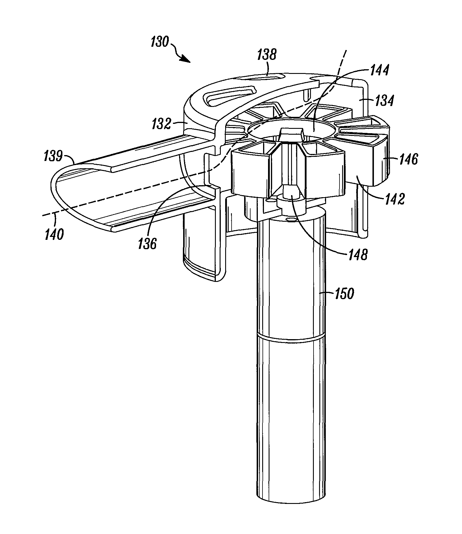
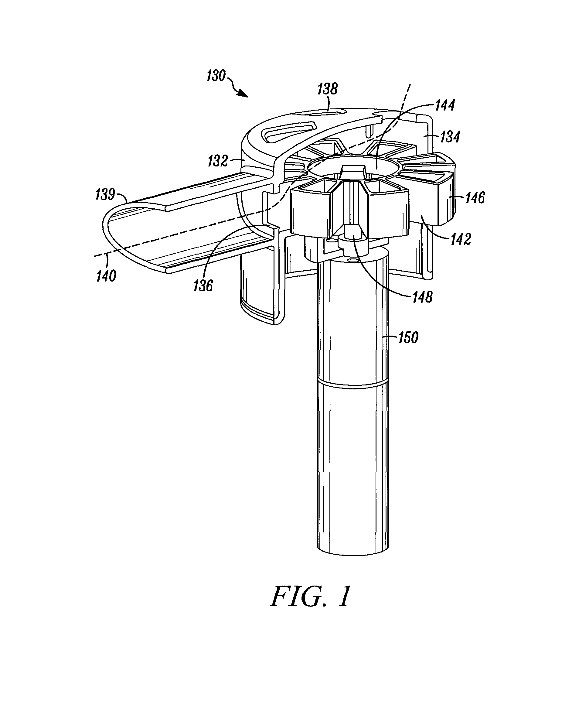
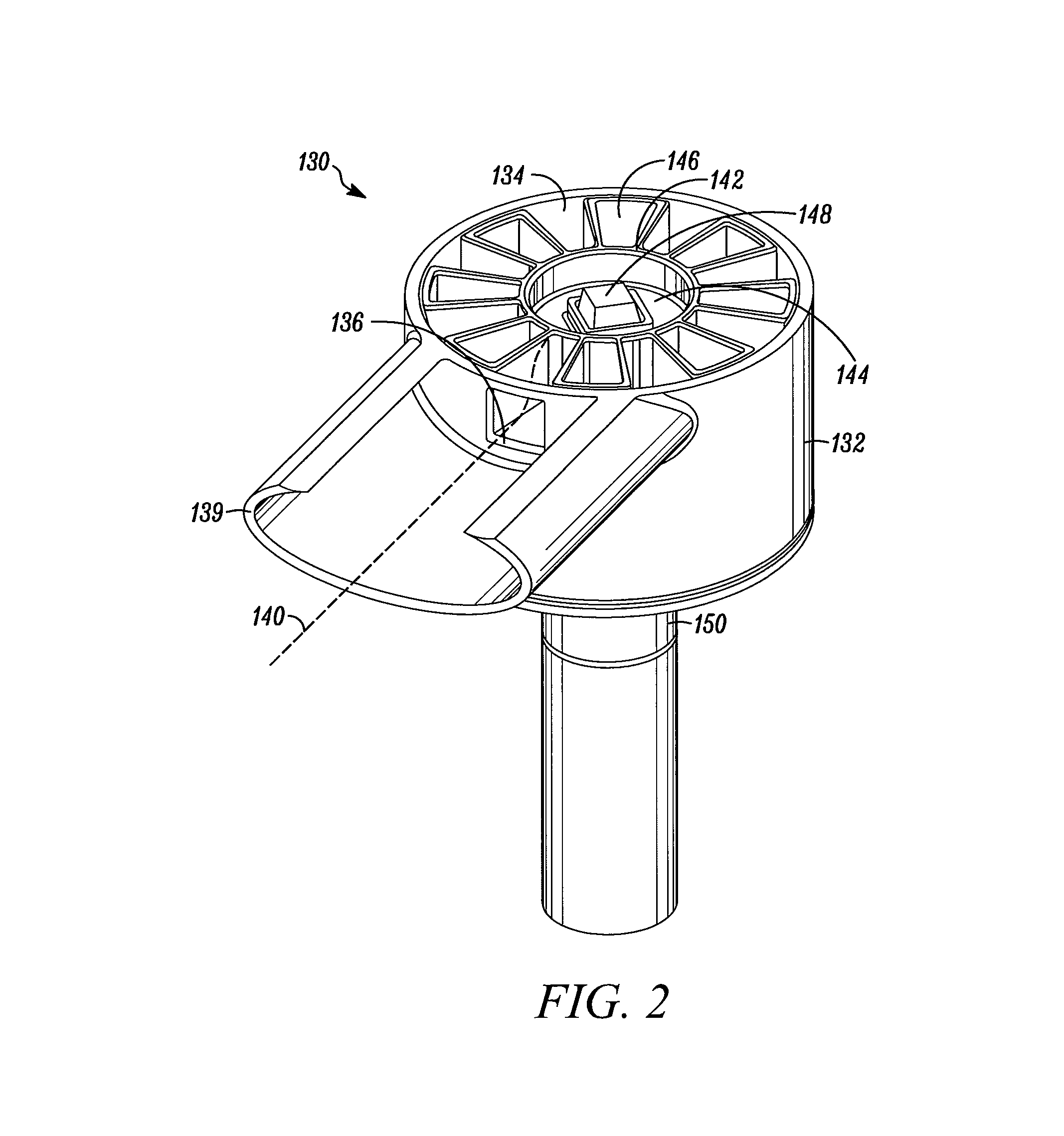
[0035]Referring to FIG. 1, an OPEP device 130 is shown with a side portion of a housing 132 removed for purposes of illustration. In general, the OPEP device 130 comprises a housing 132 having an interior chamber 134, a chamber inlet 136, and a chamber outlet 138. An exhalation flow path 140 is defined through chamber inlet 136, the interior chamber 134, and the chamber outlet 138. The housing 132 may also be associated with a mouthpiece 139 for receiving exhaled air. Although the mouthpiece 139 is shown in FIG. 1. as being fixedly attached to the housing 132, it is envisioned that the mouthpiece 139 may be removable and replaceable with a mouthpiece 139 of a different shape or size. Alternatively, other user interfaces, such as breathing tubes or gas masks (not shown) may be associated with the housing 132. Preferably, the housing 132 is openable so that the interior chamber 134 and the parts contained therein can be periodically accessed, cleaned, and replaced. The housing 132 may...

second embodiment

[0046]Referring to FIG. 6, an OPEP device 230 is shown with a side portion of a housing 232 removed for purposes of illustration. In general, the OPEP device 230 has a larger housing 232 for accommodating multiple restrictor members 242. The housing 232 also has an interior chamber 234, a chamber inlet 236, and a chamber outlet 238. A flow path 240 is defined through the chamber inlet 236, the interior chamber 234, and exiting the chamber outlet 238.

[0047]Within the interior chamber 234, the restrictor members 242 may either be stacked atop one another and operatively connected to a shaft 248, or, in the alternative, each individually connected to the shaft 248. Furthermore, each restrictor member 242 may have a different number of blocking segments 246. As in the prior embodiment, the housing 232 is openable so that a user may remove and replace the restrictor member 242 positioned adjacent the chamber inlet 236. Thus, the interior chamber 232 may conveniently store multiple restri...

third embodiment

[0049]Referring to FIGS. 7-8, an OPEP device 330 is shown. As shown in FIG. 7, the OPEP device 330 is adapted to connect to an output 360 of a nebulizer 352 for the simultaneous administration of OPEP and aerosol therapies. The OPEP device 330 generally includes a respiratory portal 354 for fluidly interconnecting the nebulizer 352, a mouthpiece 339, and the OPEP housing 332. The OPEP device 330 may be configured such that it can be used either in combination with the nebulizer 352 or solely for administration of OPEP therapy. FIG. 7 also illustrates a motor housing 356 for housing a motor (not shown) and batteries (not shown) for supplying power to the motor.

[0050]Referring to FIG. 8, a side view of the respiratory portal 354 is shown without the nebulizer 352 for delivery of OPEP therapy only. In FIG. 8, the chamber inlet 336 is located above the interior chamber 334 and the chamber outlet 338 is located directly beneath the mouthpiece 339. However, it should be noted that the cha...


PUM


Abstract

An oscillating positive respiratory pressure apparatus and a method of performing oscillating positive respiratory pressure therapy. The apparatus includes a housing having an interior chamber, a chamber inlet, a chamber outlet, an exhalation flow path defined between the inlet and the outlet, and a restrictor member rotatably mounted within the interior chamber. The restrictor member has an axis of rotation that is substantially perpendicular to the flow path at the inlet, and includes at least one blocking segment. Rotation of the restrictor member moves the at least one blocking segment between an open position and a closed position. Respiratory pressure at the chamber inlet oscillates between a minimum when the at least one blocking segment is in the open position and a maximum when the at least one blocking segment is in the closed position. By exhaling into the apparatus, oscillating positive expiratory pressure therapy is administered.

Description

RELATED APPLICATIONS[0001]This application is a continuation of U.S. application Ser. No. 12 / 472,215, filed on May 26, 2009, pending, which claims the benefit of U.S. Provisional Application No. 61 / 056,358, filed on May 27, 2008, expired, both of which are incorporated herein by reference.TECHNICAL FIELD[0002]The present disclosure relates to a respiratory treatment device, and in particular, to an oscillating positive respiratory pressure device.BACKGROUND[0003]Each day, humans may produce upwards of 30 milliliters of sputum, which is a type of bronchial secretion. Normally, an effective cough is sufficient to loosen secretions and clear them from the body's airways. However, for individuals suffering from more significant bronchial obstructions, such as collapsed airways, a single cough may be insufficient to clear the obstructions.[0004]One type of therapy, utilizing oscillating positive expiratory pressure (“OPEP”), is often used to address this issue. OPEP therapy represents an...

Claims


Application Information

Patent Timeline
Patent Type & Authority Applications(United States)
IPC IPC(8): A61M16/20A61M16/00A61M16/14
CPCA61M16/208A61M16/0057A61M16/14A61M11/06A61M16/0066A61M16/0096A61M16/0816A61M16/20A61M16/0006A61M16/0866
Inventor MEYER, ADAMENGELBRETH, DAN
Owner TRUDELL MEDICAL INT INC
Why Eureka
Try Eureka