Tire pressure monitoring system

a technology of tire pressure monitoring and monitoring system, which is applied in the direction of tire measurement, vehicle components, transportation and packaging, etc., can solve the problems of increased fuel consumption, excessive tire cost, and the biggest operating expense of trucks is the cost of tires, so as to achieve easy installation and maintenance, long battery life, and low cost

Active Publication Date: 2014-02-13
LUNDQVIST TORBJORN
View PDF8 Cites 10 Cited by
  • Summary
  • Abstract
  • Description
  • Claims
  • Application Information

AI Technical Summary

Benefits of technology

[0012]Yet another object of the invention is to provide a warning device, which can be easily individually calibrated according to the desired tire pressure.
[0042]Yet another object is to provide a safety mechanism when even tire pressure between two tires is linked and one tire is damaged by subsequently shutting off the air flow between the linked tires so that the air pressure in the undamaged tire is maintained in a drivable condition.

Problems solved by technology

One of the biggest operating expenses for trucks is the cost of tires.
With underinflated tires, the wear of tires is excessive, the fuel consumption increases, the handling characteristics of the vehicle are affected in a negative manner and the risk for catastrophic tire failure increases, and the road safety is jeopardized.
With under inflation the tires get hot and the risk for thread separation increases especially in re-threaded tires.
Although truck drivers are typically aware of the importance of having the right tire pressure, the amount of time and effort needed to properly inspect the tire pressure in all the tires often makes the driver neglect the inspection assuming that the pressure is correct.
In addition to being time consuming on the typical dual wheel rear axles it is also inconvenient since it is often necessary to be down on your knees on the ground to locate valve stems to be able to check the pressure.
Many of the aftermarket TPMS are difficult to use for the end user and to market for the distributors due to several reasons:Tire location programming.
This is a time consuming and often confusing procedure for the common user and even for the vehicle maintenance personnel.
These systems make it difficult for the distributor to provide his customer with all the right pressure ranges in advance.
However, many systems can be programmed for the warning threshold but by an often rather complicated series of inputs to the system.Very few systems allow several monitors and a capability to cross monitor several vehicles which make those systems useless for maintenance and service personnel.No systems are capable of monitoring a series of trailers waiting to be picked up by a tow vehicle such as a tractor.

Method used


Image

  • Tire pressure monitoring system
  • Tire pressure monitoring system
  • Tire pressure monitoring system

Examples


Embodiment Construction

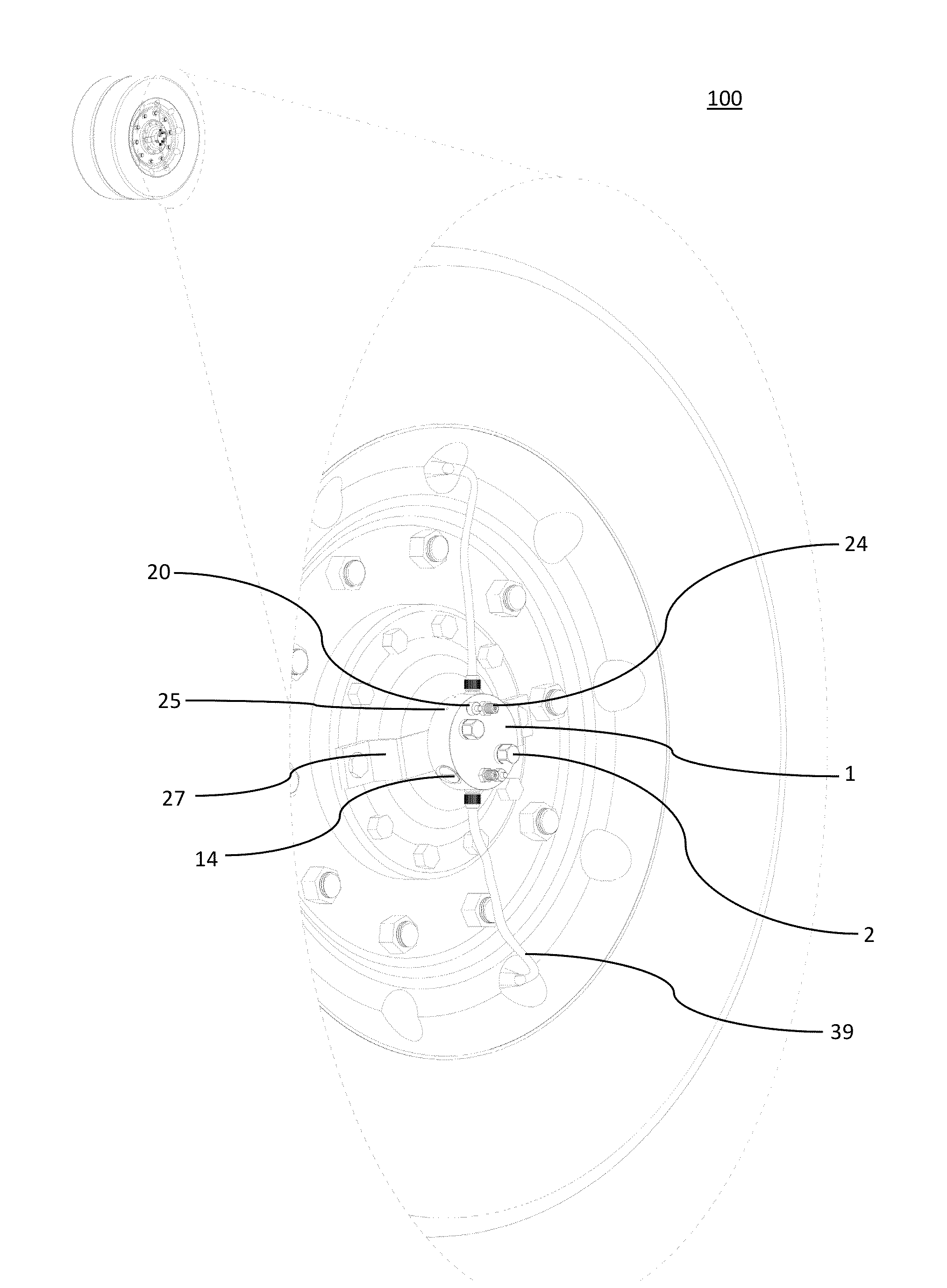
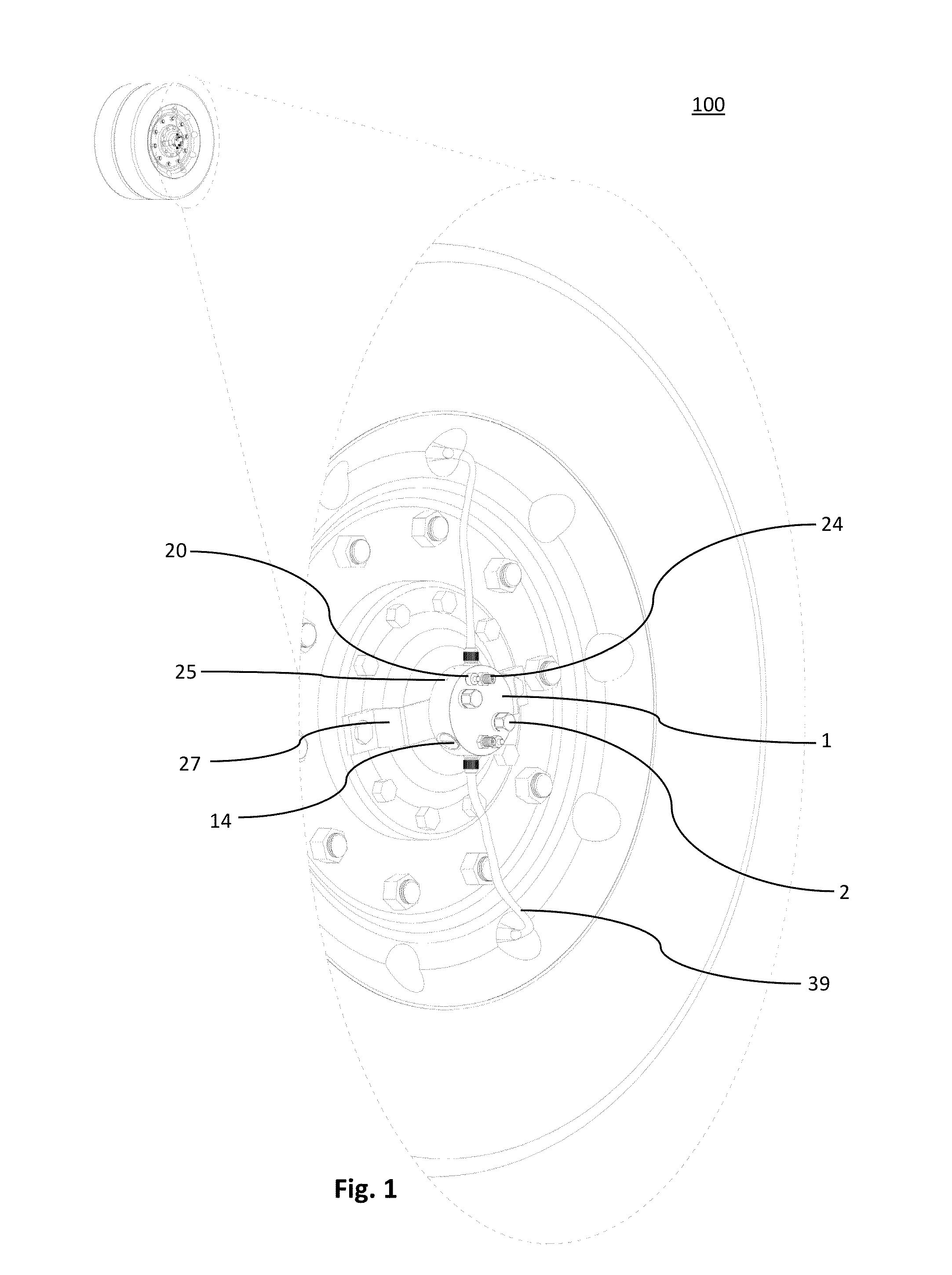
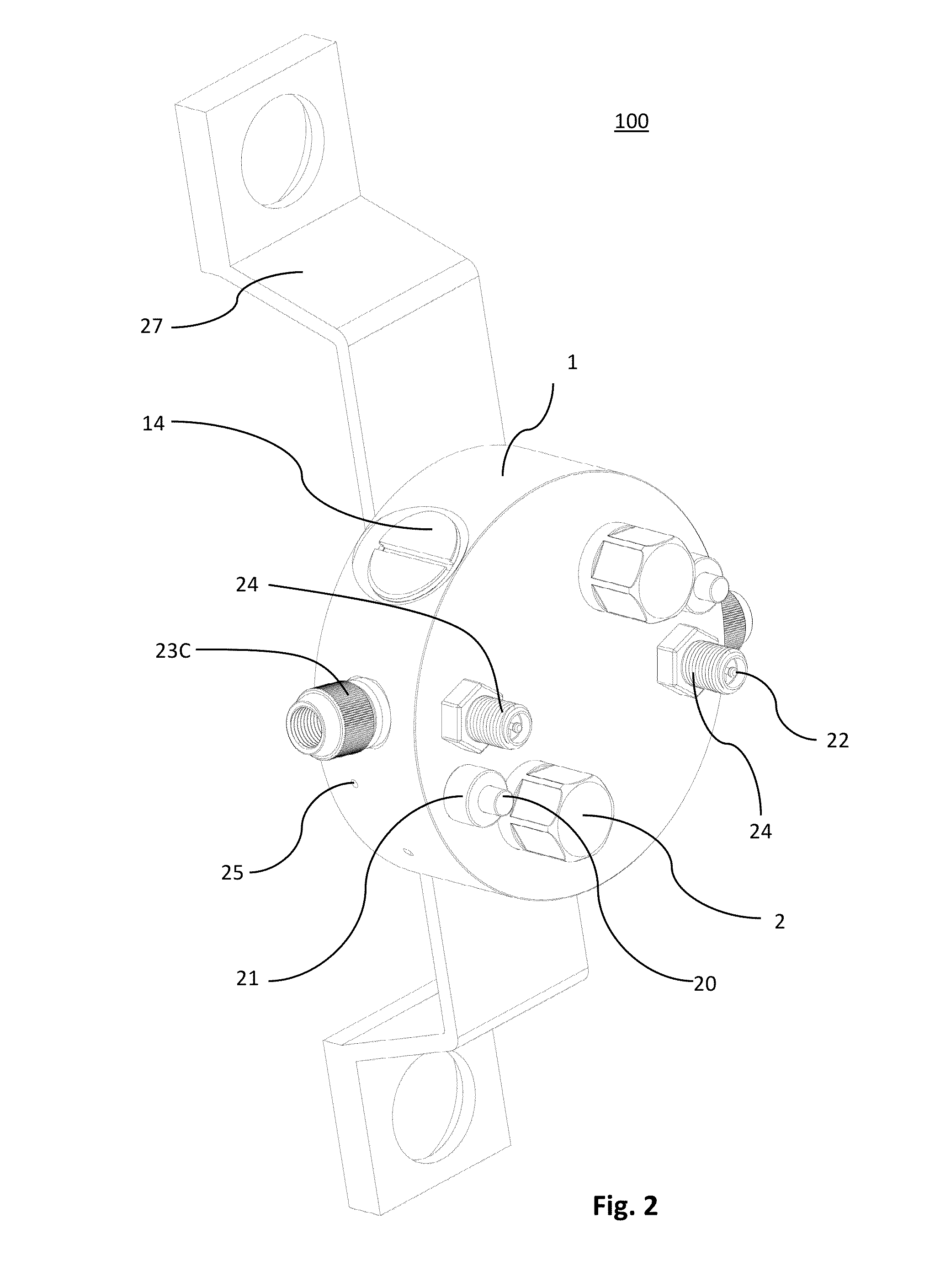
[0061]The body 1 should be machined from brass with pressure area 60 for the tire pressure and pressure channels 61 to channel the pressure into the right areas. Body 1 also has a battery cavity 62 and a test button cavity 63. Pressure area 60, valve stem 24, inlet adapter comprised of 23A, 23B, 23C and test button cavity 63 are all connected through pressure channels 61 in the body 1. The batteries 13 have a positive end 13A in contact with the battery center pin 15 and a negative end 13B completes a circuit and allows current to flow when a battery spring 16 is in contact with a battery end cap screw 14 to make the body 1 a negative conductor. The positive side is connected from the battery center pin 15 via the connector screw 37 to the connector strip 36 to the pressure chamber closing pin 10 to the pressure chamber contact spring 11 to the pressure Chamber 9 which has the membrane 7 soldered to it. If the pressure in the pressure chamber 9 is greater than the pressure in the pr...


PUM


Abstract

The invention comprises a tire pressure monitoring system. One system comprises a tire pressure monitor that signals to a user with audio alarm and visual alarm. Another component is the use of a tire air pressure balancing device with a safety trigger to ensure that dual tire systems share air but that stop sharing air in the case of rapid air pressure drop as in cases of tire blow out.

Description

PRIORITY APPLICATIONS[0001]This application claims priority to PCT application number PCT / US12 / 29575 filed Mar. 18, 2012 and to U.S. provisional patent application No. 61 / 454,483 filed on Mar. 18, 2011, the contents of which are incorporated herein.FIELD OF INVENTION[0002]The present invention relates to tire pressure monitoring systems TPMS and devices for trucks and heavy vehicles.BACKGROUND OF THE INVENTION[0003]The present invention relates particularly to tire pressure measuring devices for trucks and heavy vehicles such as tractors for hauling semi-trailers. One of the biggest operating expenses for trucks is the cost of tires. With underinflated tires, the wear of tires is excessive, the fuel consumption increases, the handling characteristics of the vehicle are affected in a negative manner and the risk for catastrophic tire failure increases, and the road safety is jeopardized. With under inflation the tires get hot and the risk for thread separation increases especially in...

Claims


Application Information

Patent Timeline
Patent Type & Authority Applications(United States)
IPC IPC(8): B60C23/04
CPCB60C23/0433B60C23/007B60C23/0406B60C23/0498B60C29/064
Inventor LUNDQVIST, TORBJORN
Owner LUNDQVIST TORBJORN
Why Eureka
Try Eureka