Integrating software solution units

Active Publication Date: 2014-02-13
SAP AG
View PDF1 Cites 1 Cited by
  • Summary
  • Abstract
  • Description
  • Claims
  • Application Information

AI Technical Summary

Problems solved by technology

However, storing the data of the one software solution unit in another disrupts transactional context of the software solution

Method used


Image

  • Integrating software solution units
  • Integrating software solution units
  • Integrating software solution units

Examples


Embodiment Construction

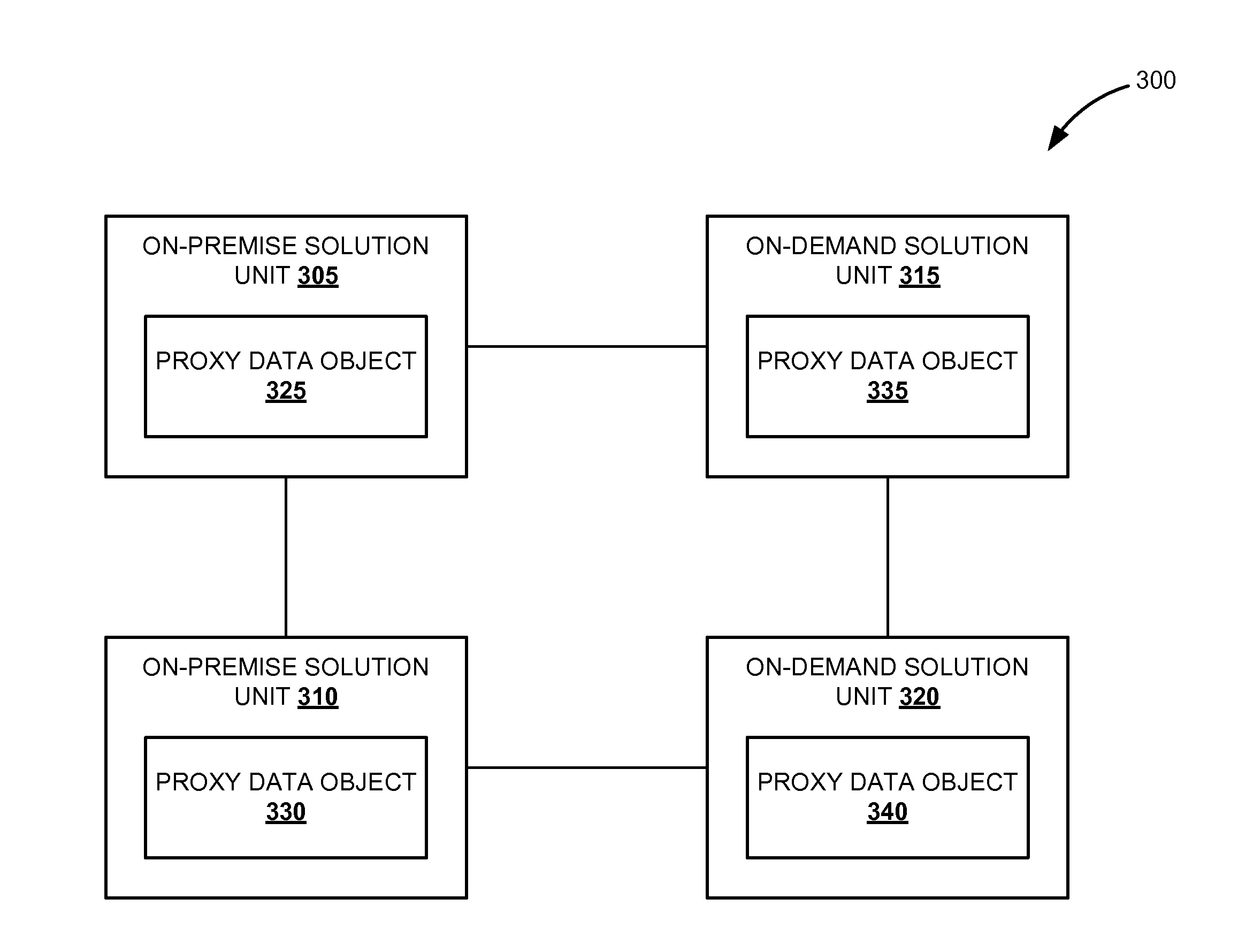
[0008]Embodiments of techniques to integrate software solution units are described herein. According to various embodiments, the software solution units can be on-premise solution units and on-demand solution units. The on-demand solution or software as a service (SaaS) is a software unit in which software and associated data pertaining to a business application are centrally stored on a remote facility such as a cloud. The cloud storage is a model of networked online storage where data is stored on multiple virtual servers. On the other hand, the on-premises solution unit is installed and associated data is stored on computers in the premises of a user or organization, rather than at the remote facility. According to one embodiment, the software solution units are integrated without disrupting transactional contexts of the software solution units.

[0009]Reference throughout this specification to “one embodiment”, “this embodiment” and similar phrases, means that a particular feature...


PUM


Abstract

In one embodiment, a proxy transactional context corresponding to a transactional context of a first software solution unit is generated. Further, a business object of a second software solution unit corresponding to the proxy transactional context is retrieved. Furthermore, the assignment of the retrieved business object to a business object of the first software solution unit is defined and the defined assignment is stored in the proxy data object. The proxy transactional context may be accessed using a remote function call and upon executing the proxy transactional context, the program returns to the transactional context. Thereby, the first software solution unit is integrated with the second software solution unit without disrupting the transactional context of the first software solution unit.

Description

FIELD[0001]Embodiments generally relate to computer systems and more particularly to methods and systems to integrate software solution units.BACKGROUND[0002]Business applications can be implemented as software solution units such as an on-premises solution unit, which is installed and associated data is stored on computers in the premises of an organization for executing a business application or as an on-demand solution unit, in which the software and associated data pertaining to the business application are centrally stored on a remote facility. Organizations select on-premise solutions and on-demand solutions for different business applications considering the requirements of the business application, and the pros and cons of the solutions. However, business applications implemented as an on-premise solution unit, such as a supplier lifecycle management (SLC), may require on-demand solution data to significantly improve the efficiency and effectiveness of the supply chains. The...

Claims


Application Information

Patent Timeline
IPC IPC(8): G06F9/46
CPCG06F9/548
Inventor KAUERAUF, BERNDZHUKOVETS, IGOR
Owner SAP AG
Why Eureka
Try Eureka