Organic Light Emitting Diode Display and Method of Driving the Same

a light-emitting diode and display technology, applied in the field of display devices, can solve the problems of non-uniformity in screen luminance and degraded image quality, and achieve the effect of high resolution

Active Publication Date: 2014-02-20
LG DISPLAY CO LTD
View PDF5 Cites 23 Cited by
  • Summary
  • Abstract
  • Description
  • Claims
  • Application Information

AI Technical Summary

Benefits of technology

[0012]An aspect of embodiments of the present invention is directed to provide an OLED display device that can compensate for the deviation of a threshold voltage and is suitable for high resolution, and a method of driving the same.

Problems solved by technology

Particularly, a current flowing in the OLED may be controlled by the driving transistor, and the threshold voltage deviation of the driving transistor and the amount of a current flowing in the OLED may be changed by various parameters, causing non-uniformity in screen luminance.
Moreover, image quality is usually degraded because the amount of a current flowing in the OLED is not uniform due to various parameters, and thus, it is typically necessary to compensate for the change in the amount of a current due to a parameter such as a source voltage.

Method used


Image

  • Organic Light Emitting Diode Display and Method of Driving the Same
  • Organic Light Emitting Diode Display and Method of Driving the Same
  • Organic Light Emitting Diode Display and Method of Driving the Same

Examples


Embodiment Construction

[0025]Hereinafter, embodiments of the present invention will be described in detail with reference to the accompanying drawings.

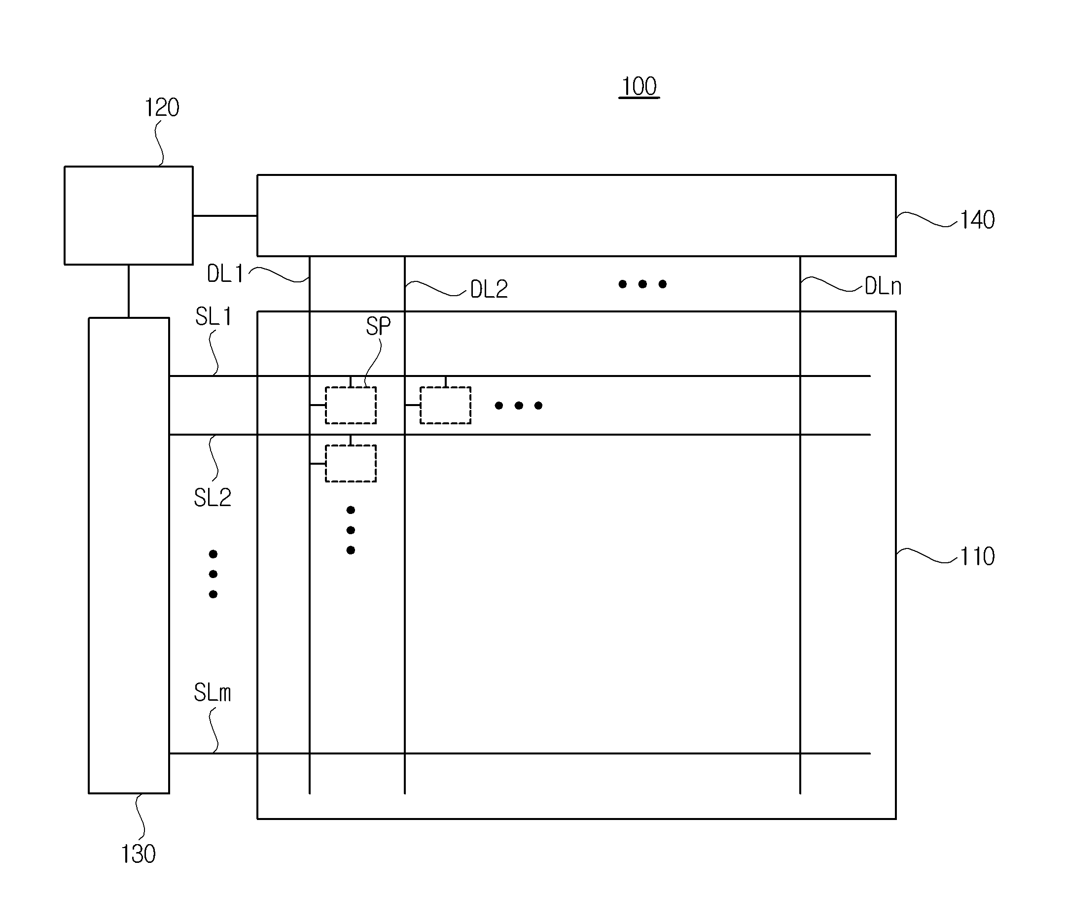
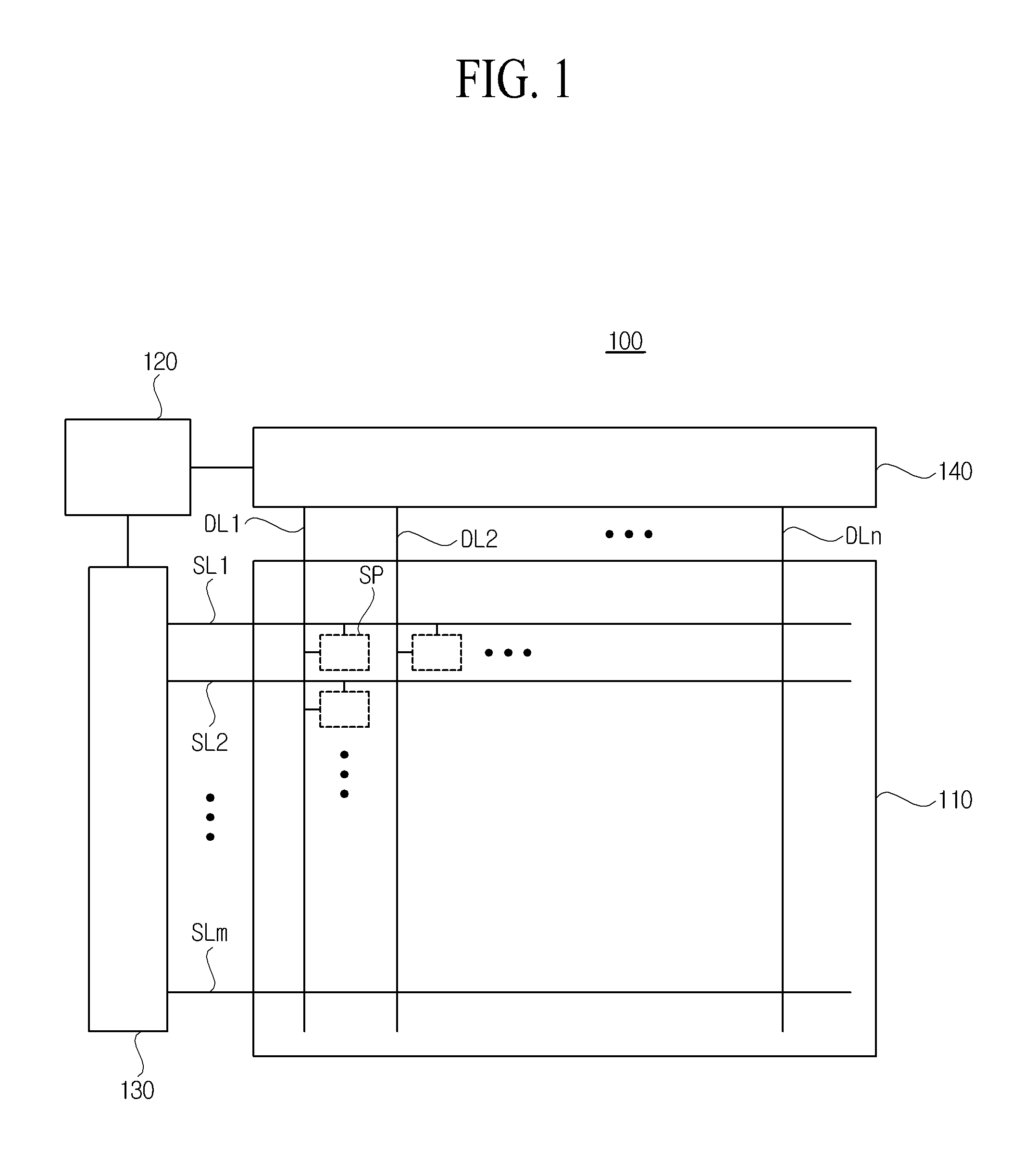
[0026]FIG. 1 is a diagram schematically illustrating a configuration of an OLED display device according to embodiments of the present invention.

[0027]As illustrated in FIG. 1, an OLED display device 100 according to embodiments of the present invention may include a panel 110, a timing controller 120, a scan driver 130, and a data driver 140.

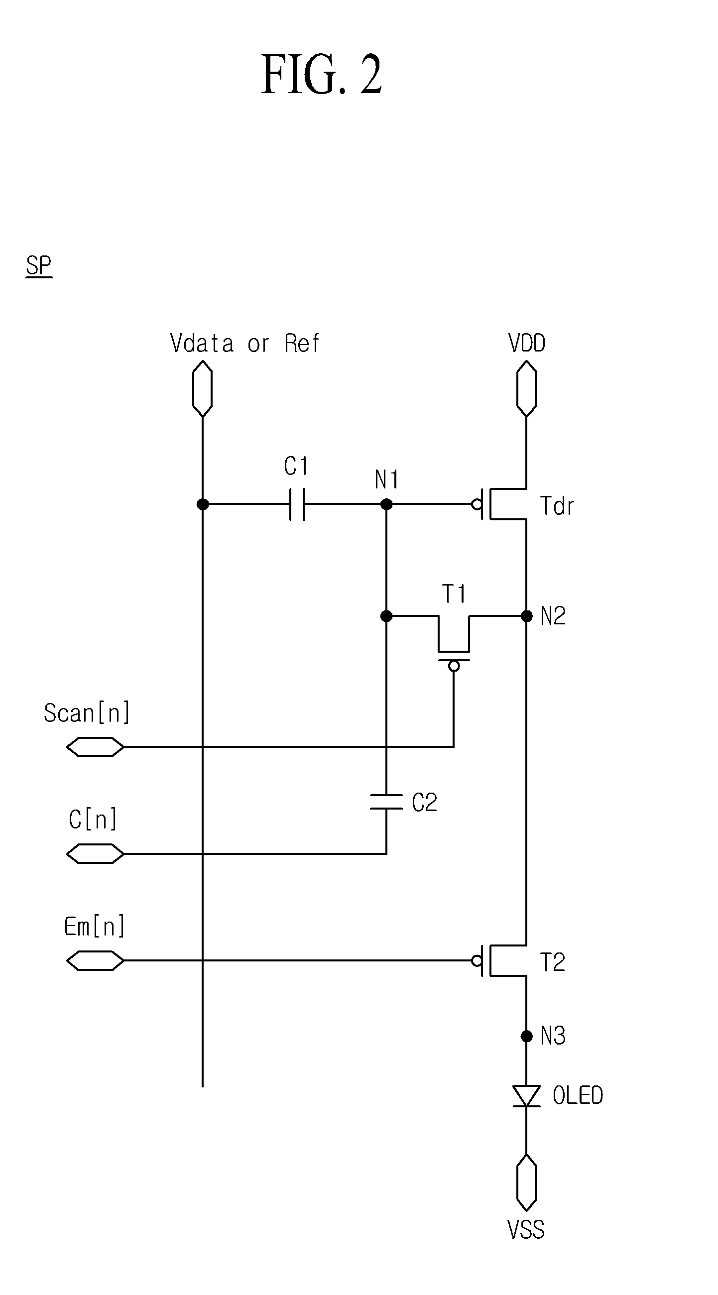
[0028]The panel 110 may include a plurality of sub-pixels SP that are arranged in a matrix type. The sub-pixels SP included in the panel 110 may emit light according to respective scan signals which are supplied through a plurality of scan lines SL1 to SLm from the scan driver 120 and respective data signals that are supplied through a plurality of data lines DL1 to DLn from the data driver 130. To this end, one sub-pixel may include an OLED, and a plurality of transistors and capacitors for driving the OLED. The detai...


PUM


Abstract

An OLED display device is provided. The OLED display device may include a first capacitor connected between a data line and a first node, a first transistor connected to the first node and a second node, an OLED connected between a low-level source voltage terminal and a third node, a second transistor connected to the second and third nodes, a driving transistor, and a second capacitor. The driving transistor may have a gate connected to the first node, a drain connected to the second node, and a source connected to a high-level source voltage terminal. One end of the second capacitor may receive a control signal, and the other end of the second capacitor may be connected to the first node.

Description

CROSS-REFERENCE TO RELATED APPLICATIONS[0001]This application claims the benefit of the Korean Patent Application No. 10-2012-0090192 filed on Aug. 17, 2012, which is hereby incorporated by reference as if fully set forth herein.BACKGROUND[0002]1. Field of the Disclosure[0003]Embodiments of the present invention relate to a display device, and more particularly, to an organic light emitting diode (OLED) display device and a method of driving the same.[0004]2. Discussion of the Related Art[0005]With the advancement of an information-oriented society, various requirements for display field are increasing, and thus, research is being conducted on various flat panel display devices that are thin, light, and have low power consumption. For example, the flat panel display devices are often categorized into liquid crystal display (LCD) devices, plasma display panel (PDP) devices, OLED display devices, etc.[0006]Particularly, some of the OLED display devices that are being actively studied ...

Claims


Application Information

Patent Timeline
Patent Type & Authority Applications(United States)
IPC IPC(8): G09G1/00
CPCG09G1/005G09G3/3225G09G3/3233G09G2230/00G09G2300/0852G09G2300/0861G09G2320/045G09G3/30
Inventor KWAK, SANG HYEON
Owner LG DISPLAY CO LTD
Why Eureka
Try Eureka