Method for determining spatial location of conducting wire and aerial earth wire of power transmission line

a technology of power transmission line and conducting wire, which is applied in the field of methods, can solve the problems of trip power failure accidents, method cannot reflect specific characteristics of lines, and cannot solve shielding failure trip rates, etc., and achieve the effect of enhancing the lighting prevention shielding efficiency of the power transmission lin

Inactive Publication Date: 2014-02-20
SHANXI ELECTRIC POWER +1
View PDF3 Cites 9 Cited by
  • Summary
  • Abstract
  • Description
  • Claims
  • Application Information

AI Technical Summary

Benefits of technology

[0022]This method calculates the shielding efficiency of the power transmission line based on that the corresponding lightning shielding failure trip rate is zero when the exposure arc is zero according to the physical locations of the various conducting wires and aerial earth wires, and determ

Problems solved by technology

Lightning strike is one of the main reasons for causing trip power failure accidents in power transmission lines.
The calculation of lightning shielding failure trip rates in the Power Industry Standards does not take into consideration the influences of the lightning discharging process, the magnitude of the lightning current and the ground elevation on the shielding efficiency, but uses an integrated averaging method empirically and according to small current test models, however, the method cannot reflect specific characteristics of the lines and cannot solve the problems of shielding failures and shielding failure trip rates being large.
Being an electric geometry analytical method established on the concept of lightning distance, the

Method used


Image

  • Method for determining spatial location of conducting wire and aerial earth wire of power transmission line
  • Method for determining spatial location of conducting wire and aerial earth wire of power transmission line
  • Method for determining spatial location of conducting wire and aerial earth wire of power transmission line

Examples


Embodiment Construction

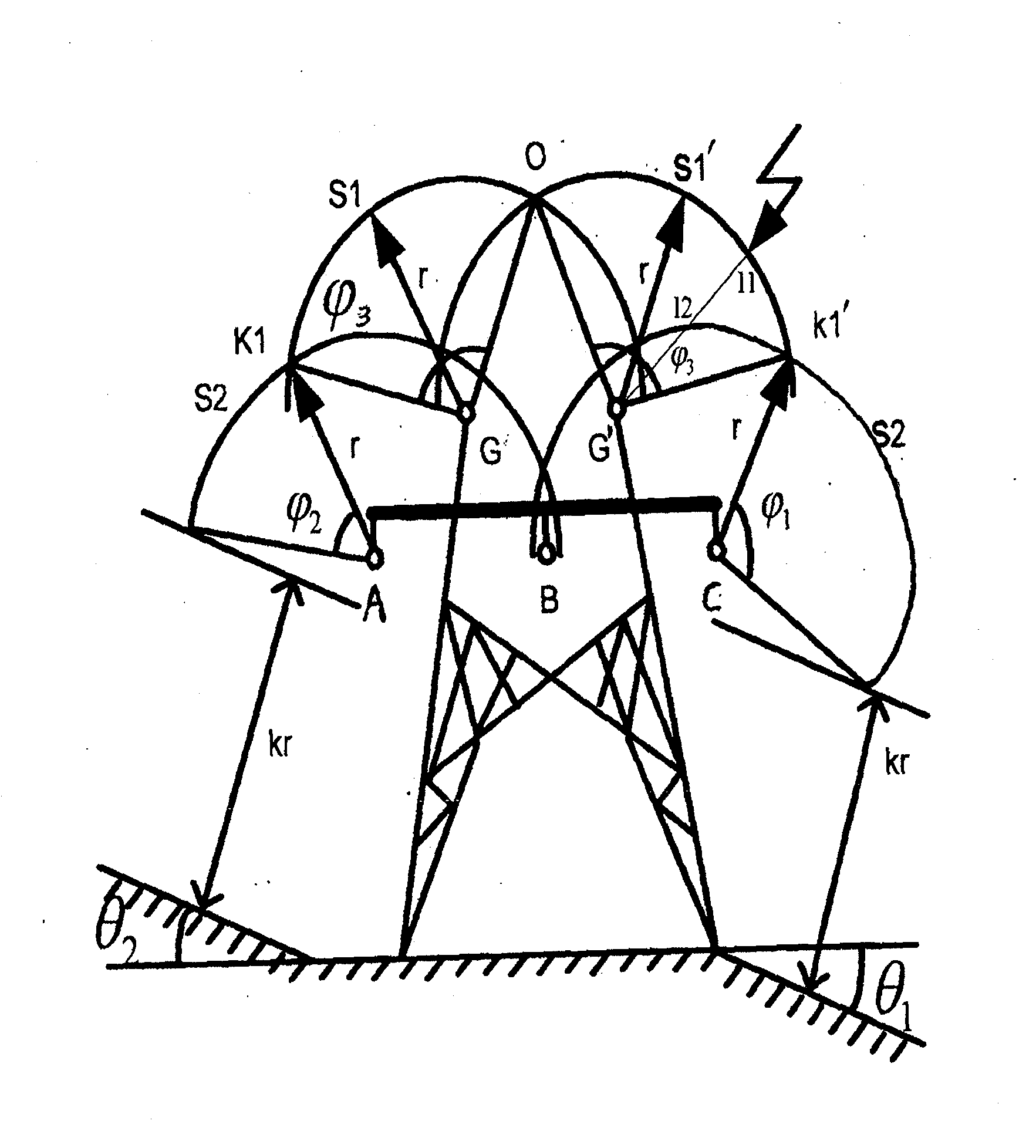
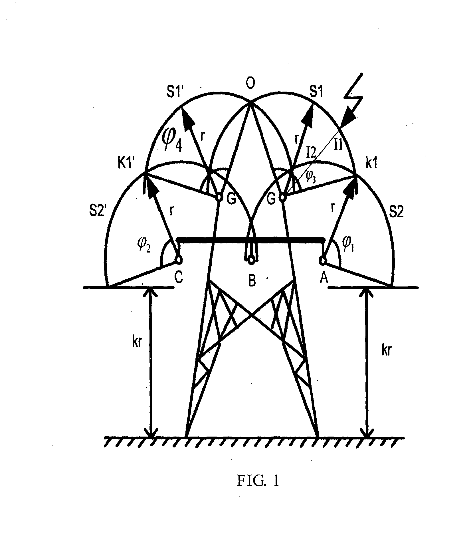
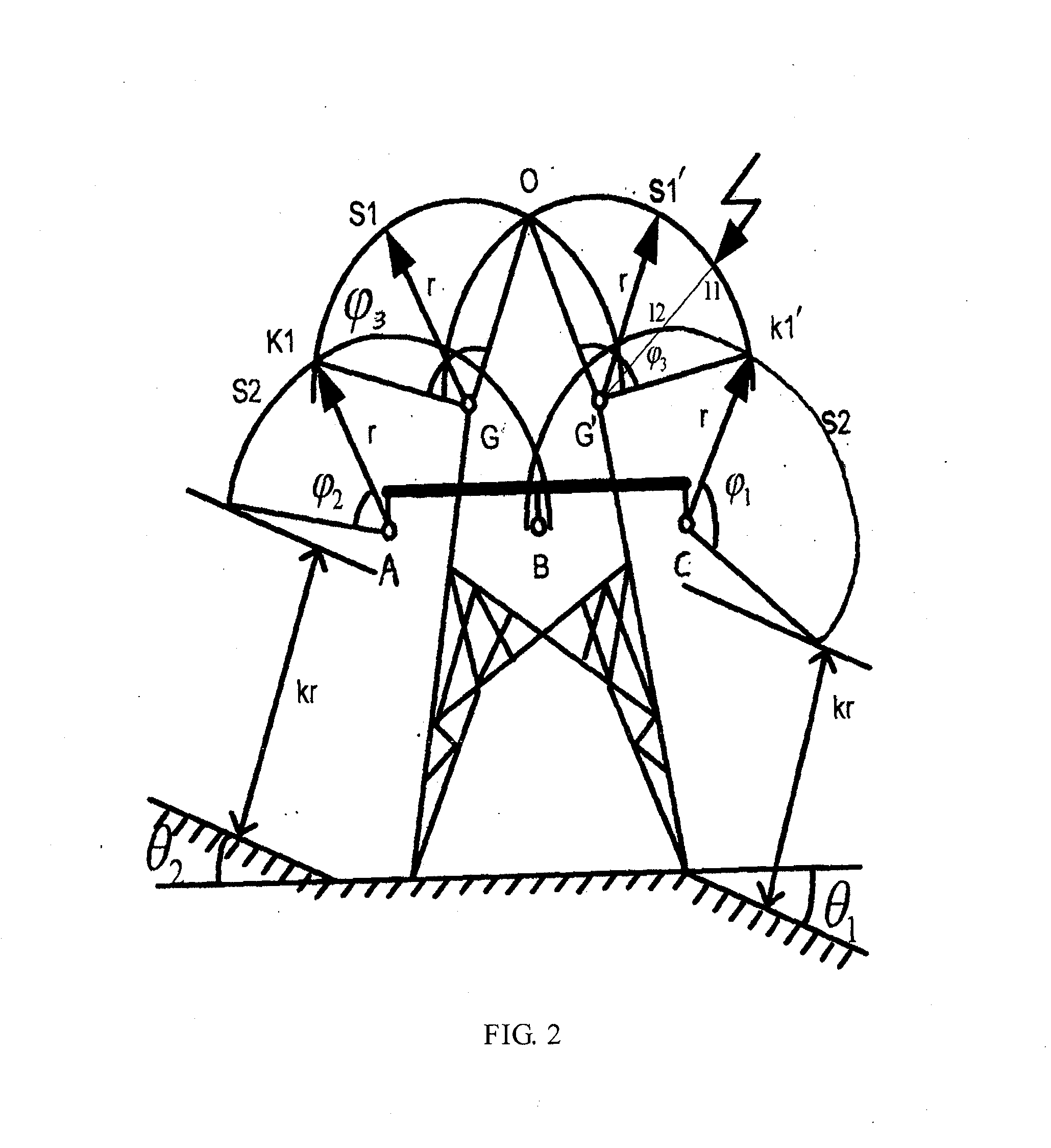
[0026]This method calculates the shielding efficiency of (single-circuit, double-circuit) power transmission lines according to the physical locations of the various conducting wires and aerial earth wires and based on that the corresponding shielding efficiency is 100% when the exposure arc length of the conducting wire is zero. The method is capable of providing designing and operating units with a reliable analytical method for preventing lightning shielding failures, and meanwhile working out the shielding efficiency of the conducting wire of each phase accurately, so as to analyze the structural relations between the aerial earth wires and the conducting wires and to determine the lightning protection effect of the whole power transmission line.

[0027]When lightning strikes a power transmission line, flashover may occur only when the overvoltage of the lightning is greater than 50% of the discharge voltage of an insulator string. Accordingly, the method calculates a shielding ra...


PUM


Abstract

Disclosed is a method for determining the spatial location of a conducting wire and an aerial earth wire of a power transmission line, so as to solve the problem that the method in the prior art is not applicable to determining the spatial location of the conducting wire and the aerial earth wire of the conventional power transmission line with respect to lightning shielding failures. In the present invention, according to the physical locations of the conducting wires and aerial earth wires, the power transmission line shielding efficiency is calculated based on that the corresponding lightning shielding failure trip rate is zero when the exposure arc is zero, thus providing designing and operating units with a reliable analytical method for preventing lightning shielding failures, and meanwhile working out the shielding efficiency of the conducting wire of each phase more accurately, so as to analyze the structural relations between the aerial earth wires and conducting wires to determine the lightning protection effect of the whole power transmission line. The present invention provides a supplementary analytical method of the shielding efficiency of the existing power transmission lines.

Description

BACKGROUND[0001]1. Field[0002]This invention relates to methods for determining conducting wires and aerial earth wires of power transmission lines, and more particularly, to a method for determining spatial locations of conducting wires and aerial earth wires of power transmission lines capable of shielding lightning shielding failures.[0003]2. Description of the Related Art[0004]Lightning strike is one of the main reasons for causing trip power failure accidents in power transmission lines. Statistically, lightning hazards account for more than 50% of all accidents in power grid systems. Therefore, protection design against the lighting strike for power transmission lines is of great importance to safe and stable operation of power grid systems. Currently, the design and performance estimation of lightning shielding systems for power transmission lines in China are based on the DL / T620-1997, Overvoltage and Insulation Coordination of AC Electric Devices, of the Power Industry Stan...

Claims


Application Information

Patent Timeline
IPC IPC(8): G01V3/38G01R31/08
CPCG01R31/08G01V3/38H02G7/20G06F30/367
Inventor TANG, ZHENWANG, KANGINGJIA, YUJUNXU, JIANGUOQI, YUEWENWAN, XUEZHIGUO, HONGLONGWEI, SHIKAICHANG, MEISHENGZHAO, XINGYONGLIAN, JIANHUAMI, YONGMI, KANGMINFENG, AIXIANGYANG, HUAWANG, HAUWANG, HONGWEIWANG, TIANZHENG
Owner SHANXI ELECTRIC POWER
Why Eureka
Try Eureka