Illuminating device

Inactive Publication Date: 2014-02-27
PHOSTEK INC
View PDF5 Cites 3 Cited by
  • Summary
  • Abstract
  • Description
  • Claims
  • Application Information

AI Technical Summary

Benefits of technology

[0006]In view of the foregoing, it is an object of the embodiment of the present invention to provide an illuminating device in absenc

Problems solved by technology

However, a driving circuit adapted for high-power LED illumination applications (e.g., LED street lamps) normally has a lifeti

Method used


Image

  • Illuminating device
  • Illuminating device
  • Illuminating device

Examples


Embodiment Construction

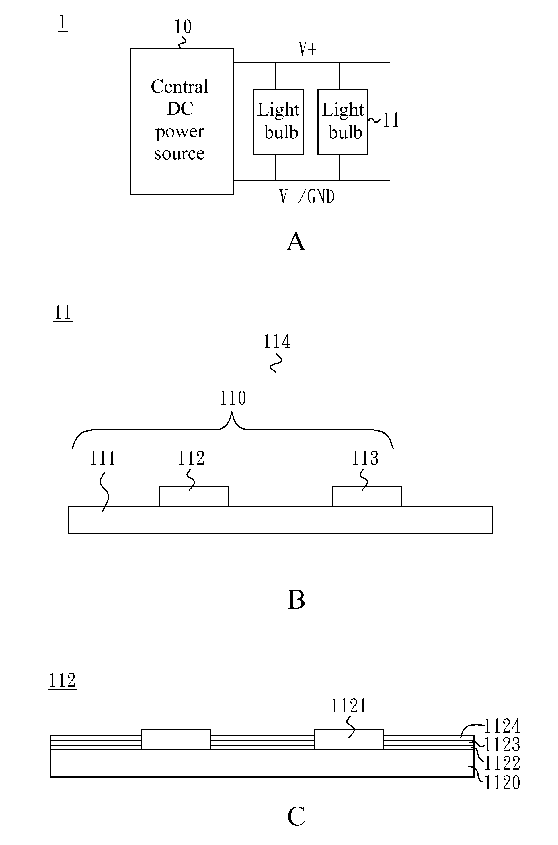
[0019]FIG. 1A shows a block diagram illustrative of an illuminating device 1 according to a first embodiment of the present invention. In the embodiment, the illuminating device 1 may include at least one light bulb 11 connected in parallel. The light bulb 11 may, for example, be a candle light. The illuminating device 1 may also include a central direct-current (DC) power source 10, having a first power terminal V+ and a second power terminal V− (or ground terminal GND), configured to provide DC voltage to the at least one light bulb 11. The DC voltage provided by the central DC power source 10 is substantially stable (having tolerable variation of ±10%, and preferably ±5%) such that each light bulb 11 may operate at its preferred condition with little power consumption and high reliability.

[0020]A DC power system may commonly provide DC voltages of 12V, 24V, 48V, 110V, 220V, and / or 380V, with respect to different transmission distances, in consideration of better LED operation and...


PUM


Abstract

An illuminating device includes at least one light-emitting source. The light-emitting source includes a substrate; at least one light-emitting chip disposed on the substrate; and at least one constant-current component electrically coupled to the light-emitting chip. The light-emitting chip includes multiple light-emitting units that are electrically coupled in series, in parallel, or in series-parallel; a first-type electrode, disposed on at least one of the light-emitting units, for electrically coupling to a central DC power source; a second-type electrode disposed on at least one light-emitting unit different from the one, on which the first-type electrode is disposed; and a tapped point configured for electrically coupling at least one of the light-emitting units to the constant-current component.

Description

BACKGROUND OF THE INVENTION[0001]1. Field of the Invention[0002]The disclosure generally relates to an illuminating device, and more particularly to a light-emitting diode (LED) illuminating device.[0003]2. Description of Related Art[0004]Light-emitting diodes (LEDs) have been widely applied for illumination purposes as their luminous efficiency is greatly enhanced and cost / price is considerably reduced. LEDs have, in theory, a lifetime over seventy thousand hours. However, a driving circuit adapted for high-power LED illumination applications (e.g., LED street lamps) normally has a lifetime less than ten thousand hours, therefore substantially affecting reliability or increasing maintenance cost of the LED lamps. One of the reasons is that an electrolytic capacitor (e.g., aluminum electrolytic capacitor) should be used at an output end of the driving circuit to reduce output ripple so that flicking phenomena is blocked. The lifetime of the aluminum electrolytic capacitor is substan...

Claims


Application Information

Patent Timeline
IPC IPC(8): H05B33/08H05B44/00
CPCH05B33/0806H01L25/075H01L2924/0002H01L33/50H01L33/62H05B45/46H05B45/37H05B45/345H01L2924/00
Inventor SHAO, SHIH-FENGCHANG, YUAN-HSIAOYANG, SHIH TSUN
Owner PHOSTEK INC
Why Eureka
Try Eureka