Sharpening device for cutting blade

a technology of sharpening device and cutting blade, which is applied in the direction of grinding/polishing apparatus, grinding machine, other manufacturing equipment/tools, etc., can solve the problems of no use of ceramic blade solutions, unsatisfactory quality, and difficulty in achieving the effect of simple and effective making

Active Publication Date: 2014-02-27
MENEGON ENNIO
View PDF22 Cites 7 Cited by
  • Summary
  • Abstract
  • Description
  • Claims
  • Application Information

AI Technical Summary

Benefits of technology

[0014]The object of the present invention is to obviate the above drawbacks, by providing a sharpening device for cutting blades that is effective and simple and inexpensive to make.

Problems solved by technology

Nevertheless, such common solution still suffer from certain drawbacks.
A first drawback consists in that rigid grinding rollers provide a cutting blade having a sharp-edged profile, whose quality is not always acceptable.
Furthermore, these solutions are of no use for ceramic blades, due to the greater fragility of the latter.
An additional drawback of these known solutions is that, during sharpening, the blade has to be pressed against the roller, and is thus heated, which may cause loss of hardness of the material, usually steel.
Yet another drawback is that the top-to-bottom rotation of the grinding surfaces of the rollers causes burr build-up, that forces frequent process stops for burr removal.
A further drawback is that prior art sharpening devices are mounted to fixed shells which set an operating position thereof, and introduction of the blades to be sharpened from both sharpening sides between the grinding members, for better sharpening, requires users to repeatedly move around the device for direct access to each side.
Another drawback is that, during blade sharpening, the user that holds the blades may inadvertently introduce them through an excessive distance between the grinding members, with the blade handles possibly contacting the latter and being damaged by their fast rotation, as soon as contact occurs.
Furthermore, prior art sharpening devices have no protection means, which might prevent the user from accidentally contacting the grinding members also by their hands during operation.

Method used


Image

  • Sharpening device for cutting blade
  • Sharpening device for cutting blade
  • Sharpening device for cutting blade

Examples


Embodiment Construction

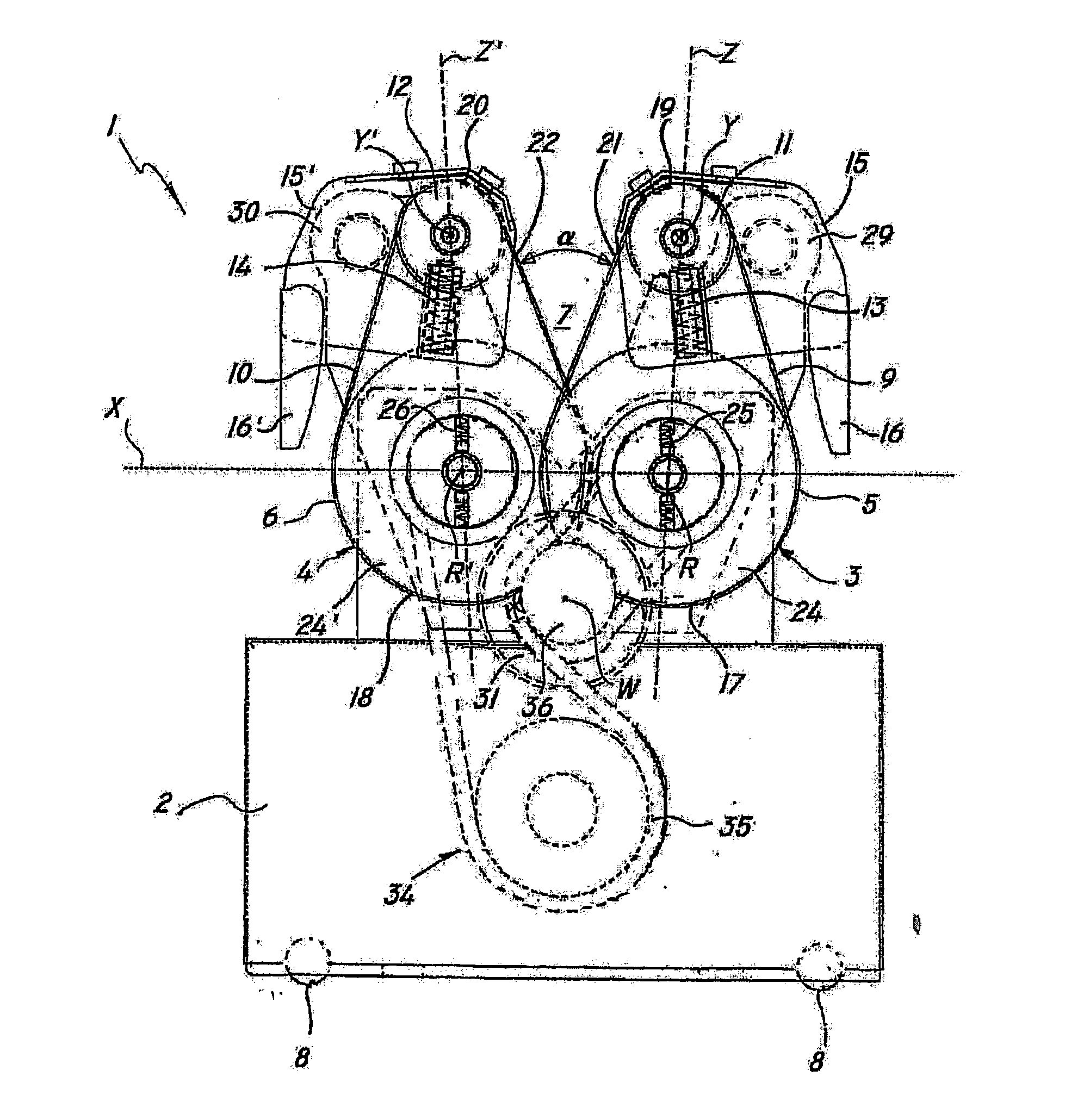
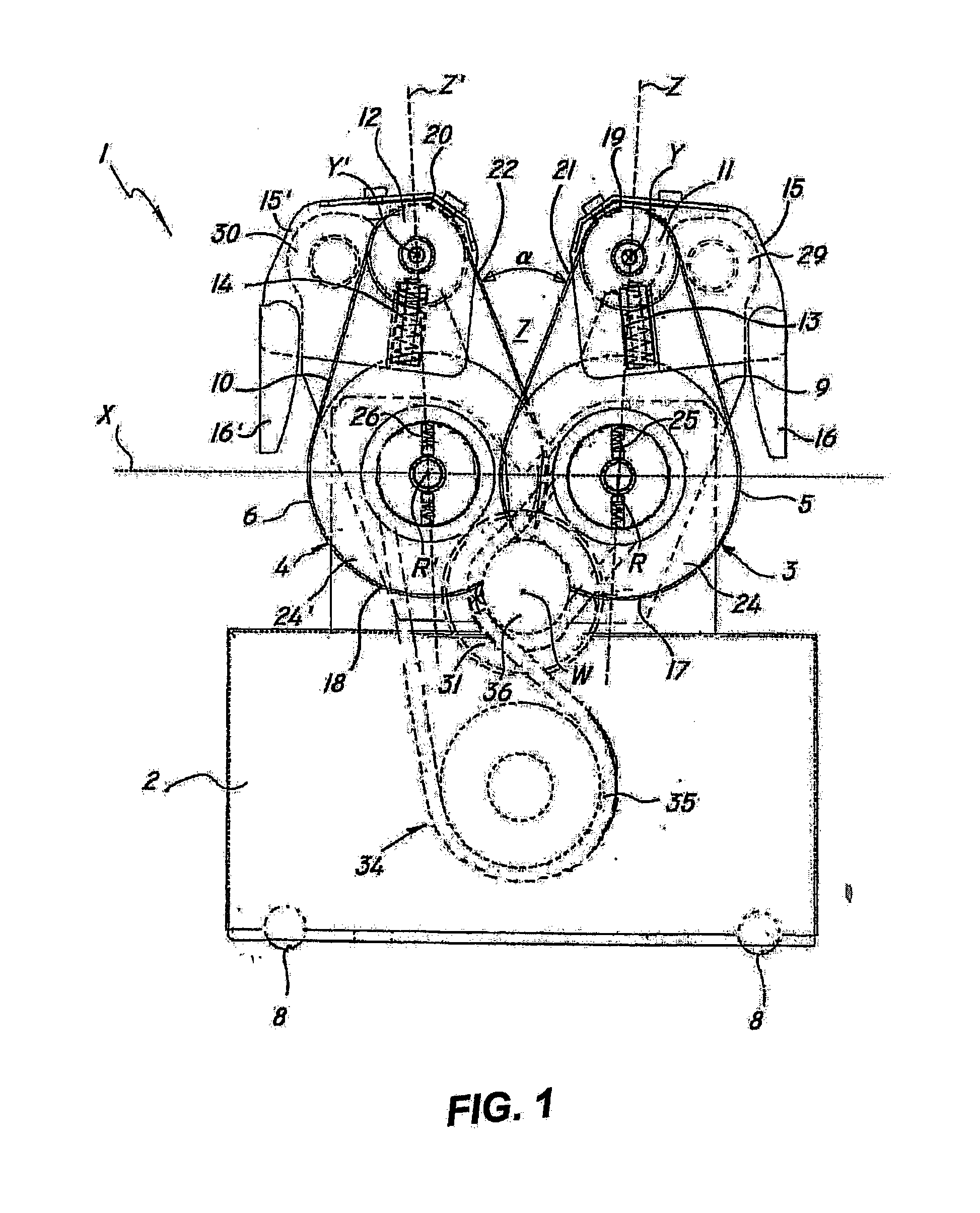
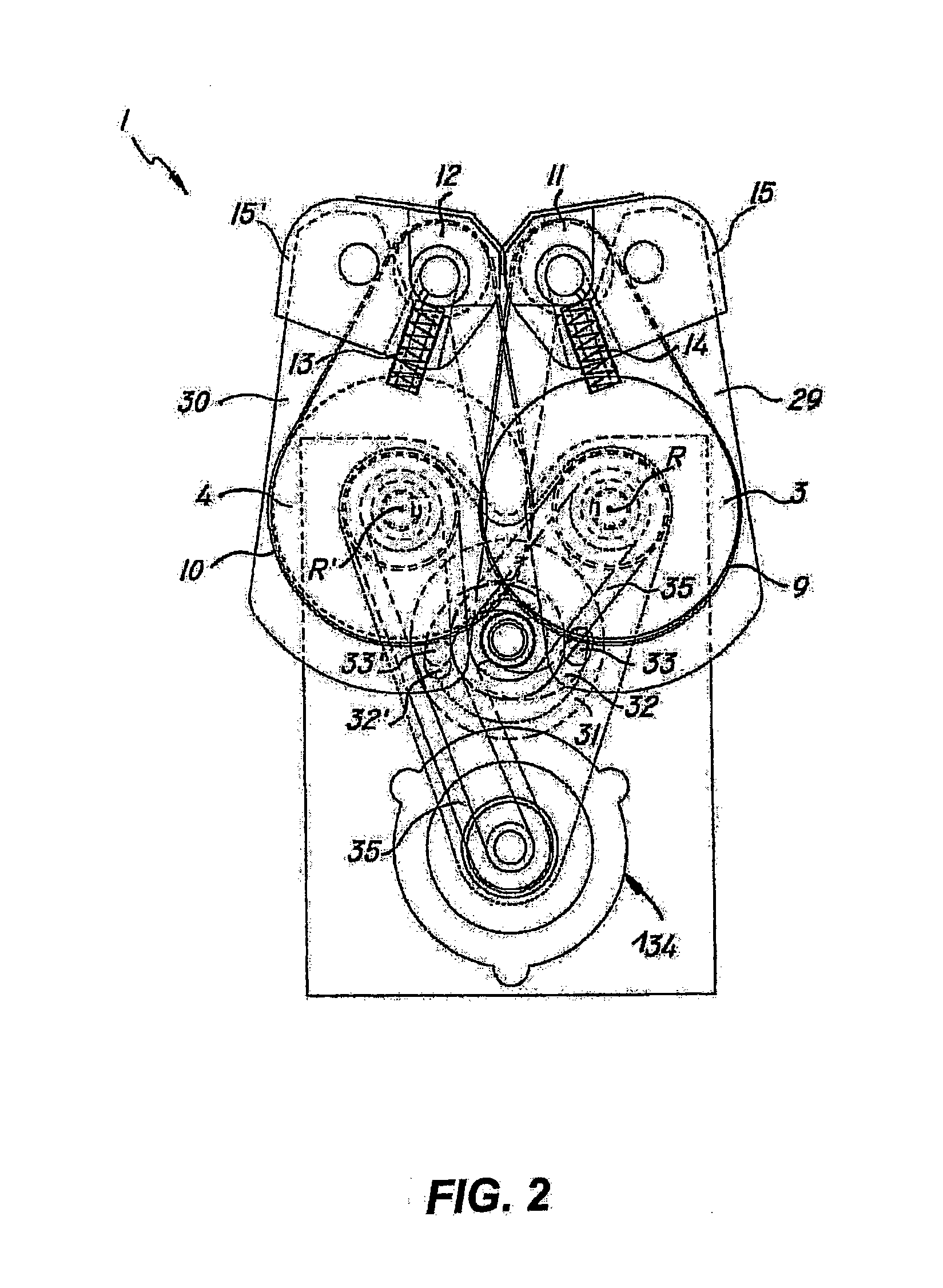
[0040]Referring to FIGS. 1 to 6, a blade sharpening device of the invention, generally designated by numeral 1, may be used for sharpening cutting blades of knives, scissors or similar tools for domestic or handicraft use.

[0041]As shown in the annexed figures, a device 1 of the invention comprises a support shell 2 with at least two rollers 3, 4 mounted thereto for rotation about respective first axes of rotation R, R′ which are substantially parallel and have a preferably, but not exclusively horizontal orientation.

[0042]The first axes of rotation R, R′ of the rollers 3, 4 are also offset in a first center-to-center direction “X”, which is substantially radial and horizontally oriented, with a predetermined center-to-center distance preferably not larger than the maximum diameter of the rollers 3, 4.

[0043]The latter are preferably disk-shaped with substantially identical radiuses and have contiguous peripheral grinding surfaces 5, 6 delimiting a working zone 7 for receiving a blade...


PUM

PropertyMeasurementUnit
angleaaaaaaaaaa
angleaaaaaaaaaa
flexibleaaaaaaaaaa

Abstract

A sharpening device for cutting blades includes a support shell, at least two rollers rotatably mounted to the shell for rotating about respective substantially parallel first rotation axes and offset along a first substantially radial center-to-center direction, the rollers having respective contiguous grinding peripheral surfaces delimiting a working zone designed to receive a blade to be sharpened, the grinding surfaces being elastically yieldable to conform to the profile of the blade.

Description

FIELD OF THE INVENTION[0001]The present invention generally finds application in the field of hard material machining devices and particularly relates to a sharpening device for cutting blades, particularly of the type designed for domestic or handicraft use.BACKGROUND ART[0002]Blade sharpening devices are known which have two or more pairs of grinding rollers or wheels located in mutually facing positions with their respective lateral grinding surfaces in adjacent relation.[0003]The cutting blade is sharpened by being interposed between the two rollers with the blade edge contacting the grinding surfaces and causing the rollers to rotate about respective parallel axes with opposite directions of rotation.[0004]EP 2,014,414 discloses a knife sharpening device that comprises two endless abrasive belts which are mounted in a closed-loop configuration to a drive unit comprising two respective pairs of motorized pulleys in such arrangement as to cause two active branches of the abrasive...

Claims


Application Information

Patent Timeline
Patent Type & Authority Applications(United States)
IPC IPC(8): B24B21/00B24B27/00B24B3/54
CPCB24B21/002B24B27/0076B24B3/54
Inventor MENEGON, ENNIO
Owner MENEGON ENNIO
Why Eureka
Try Eureka