Hydraulic accumulator health monitor

a technology of accumulator and health monitor, which is applied in the direction of fluid couplings, couplings, mechanical equipment, etc., can solve the problems of degree of error that may be associated with the operation health

Inactive Publication Date: 2014-03-06
CATERPILLAR INC
View PDF1 Cites 85 Cited by
  • Summary
  • Abstract
  • Description
  • Claims
  • Application Information

AI Technical Summary

Problems solved by technology

The degree of error may be associated with the

Method used


Image

  • Hydraulic accumulator health monitor
  • Hydraulic accumulator health monitor
  • Hydraulic accumulator health monitor

Examples


Embodiment Construction

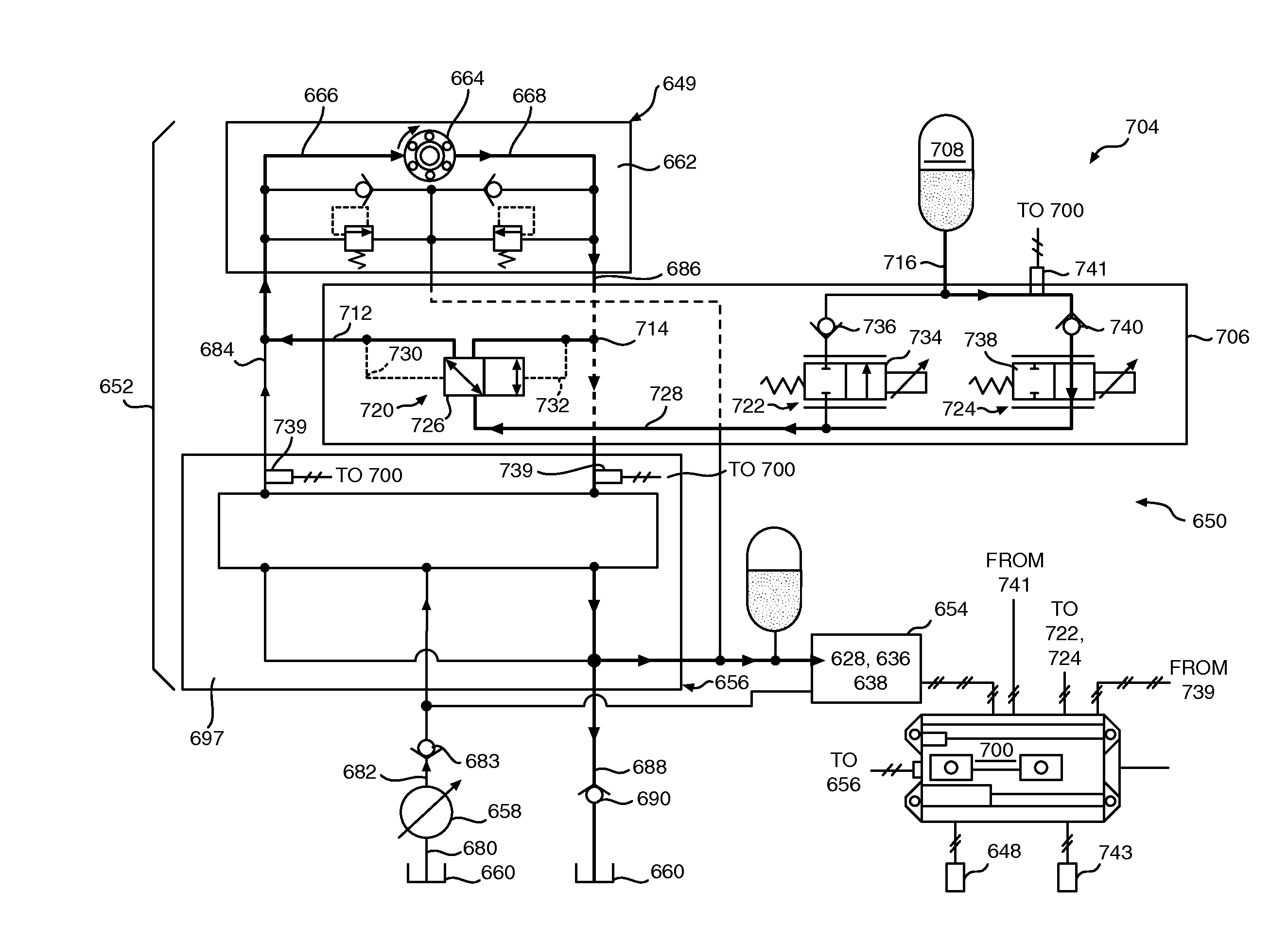
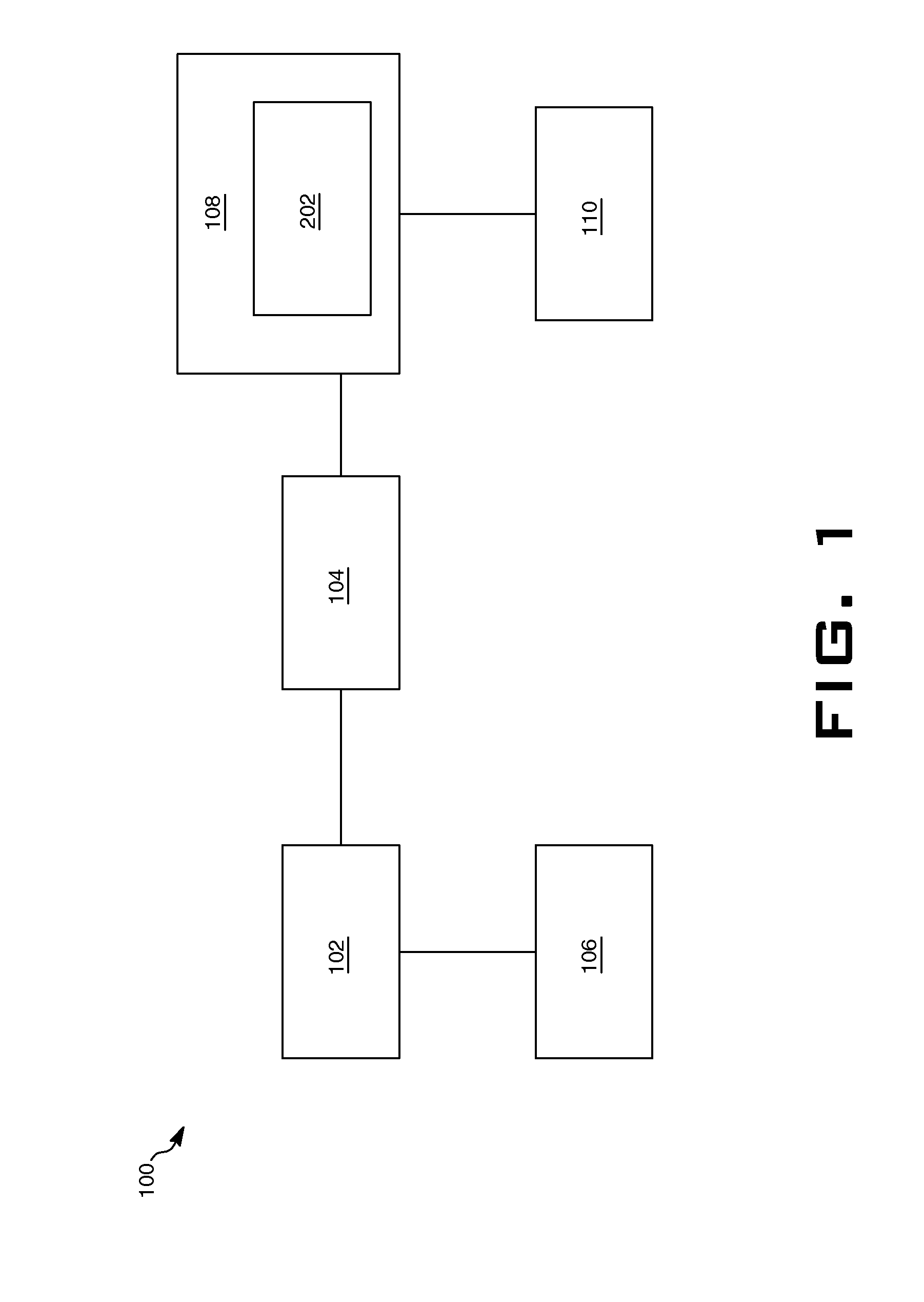
[0016]FIG. 1 illustrates an exemplary system 100 including a hydraulic accumulator 102, a pressure sensor 104, a fluid source 106 and a controller 108, according to one embodiment of the present disclosure. The system 100 may be embodied in any machine such as excavators, wheel loaders, tractors and other machinery. The hydraulic accumulator 102 may be a piston-based accumulator, a bladder-based accumulator, membrane / spring-biased accumulator, or other kind of pressurized fluid storage device that can be selectively charged and discharged. One or more valves (not shown) may be associated with the system 100 to selectively control charging and discharging of the accumulator. For example, one or more valves may be open to permit charging and / or discharging of the accumulator, whereas one or more valves (same or different) may be closed to permit charging and / or discharging.

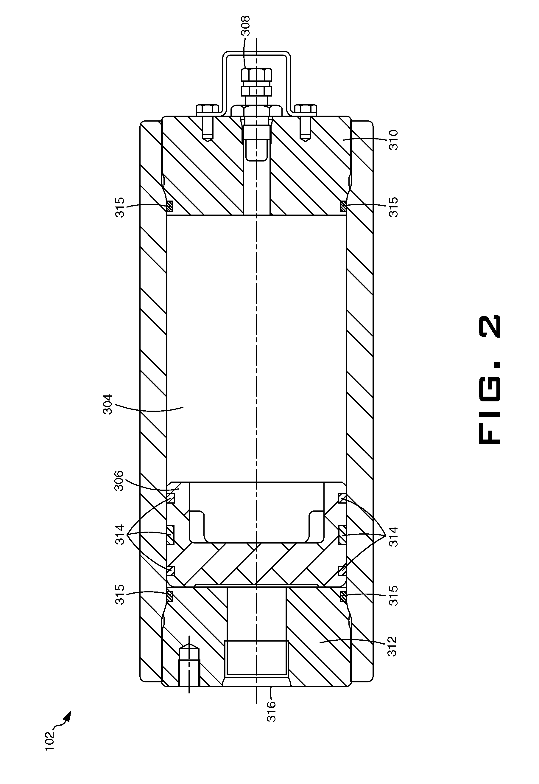
[0017]Hydraulic accumulator 102 may embody pressure vessels filled with a compressible gas that are configured to...


PUM


Abstract

A system and method to diagnose the operational health of a hydraulic accumulator are provided. The system can include a hydraulic accumulator selectively coupled to a hydraulic actuator, such as a swing motor. The accumulator can be charged by movement of the actuator. A pressure sensor can be associated with the accumulator to determine an accumulator pressure. A controller can be connected to the pressure sensor. The controller can determine a charge curve based on a relationship between an actuator operational parameter associated with the actuator movement and the accumulator pressure. The controller can compare the charge curve to a previously defined charge curve or range to determine an error between the charge curve and the previously defined charge curve or range. The degree of the error can be associated with the operational health of the accumulator, and if too large, the operator may be notified of the status.

Description

RELATED APPLICATIONS[0001]This application is based upon and claims the benefit of priority from U.S. Provisional Application No. 61 / 695,344 by Pengfei Ma et al., filed Aug. 31, 2013, the contents of which are expressly incorporated herein by reference.TECHNICAL FIELD[0002]The present disclosure relates to hydraulic accumulators and more particularly to monitoring and determining the health of the hydraulic accumulator.BACKGROUND[0003]Pre-charge pressure of a hydraulic accumulator needs to be periodically checked after installation in a hydraulic system to ensure operational health of the accumulator. Typical solutions for detecting the accumulator health involve connecting a gas pressure gauge and / or a modular kit to a gas valve of the hydraulic accumulator, when the machine is stopped and the fluid in the hydraulic accumulator is not pressurized. The gas pressure gauge provides a reading of the pre-charge pressure. Depending on such readings, the hydraulic accumulator is either re...

Claims


Application Information

Patent Timeline
IPC IPC(8): E02F9/12
CPCE02F9/123E02F9/2025E02F9/2217E02F9/2296F15B1/024F15B1/033F15B1/24F15B19/005F15B2201/31F15B2201/505F15B2201/51F15B2211/625F15B2211/6306F15B2211/6653F15B2211/7058F15B2211/855F15B2211/857F15B2211/87
Inventor MA, PENGFEICHEN, DAYAOPETERSON, RANDAL
Owner CATERPILLAR INC
Why Eureka
Try Eureka