Bike extendable crank

Inactive Publication Date: 2014-03-13
CHANG SHUN JIE
View PDF2 Cites 0 Cited by
  • Summary
  • Abstract
  • Description
  • Claims
  • Application Information

AI Technical Summary

Benefits of technology

[0005]The primary object of the present invention is to provide a bike extendable crank which comprises at least one extendable crank unit and at least one cam unit. Each extendable crank unit comprises an immovable crank and a movable crank. The immovable crank has a slide trough therein, a limit groove at one side thereof, and a main axle hole above the limit groove. One end of the movable crank has a first pivot hole for connection of a pedal, and another end of the movable crank has a second pivot hole for connection a guide axle. The movable crank is slidably received in the slide trough of the immovable crank. The guide axle inserting through the second pivot hole of the movable crank slides in the limit groove of the immovable crank. The cam unit comprises a support, a retainer, an inner cam and an outer cam. The support has a pivot hole. At least two supports are connected to the retainer. The outer cam has a track guide trough therein and an outer cam track at the edge of the track guide trough. The inner cam has a guide hole. The inner cam has an inner cam track at a circumferential edge thereof. The inner cam track is less than the outer cam track of the track guide trough. At least two outer cams are respectively connected to two sides of the support. The inner cam is disposed in the track guide trough of the outer ca

Problems solved by technology

In this way, it is labor-savi

Method used


Image

  • Bike extendable crank
  • Bike extendable crank
  • Bike extendable crank

Examples


Embodiment Construction

[0016]Embodiments of the present invention will now be described, by way of example only, with reference to the accompanying drawings.

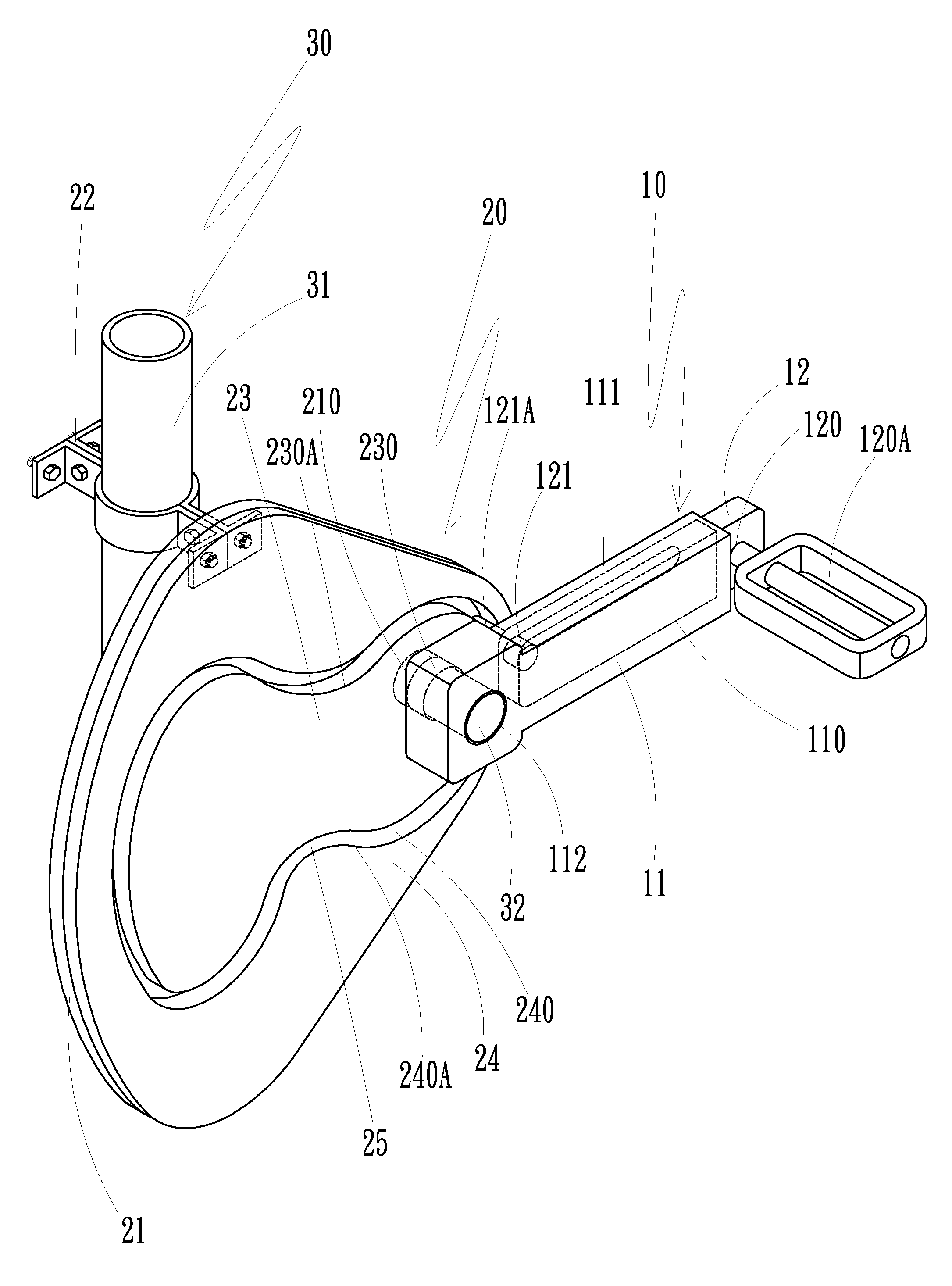
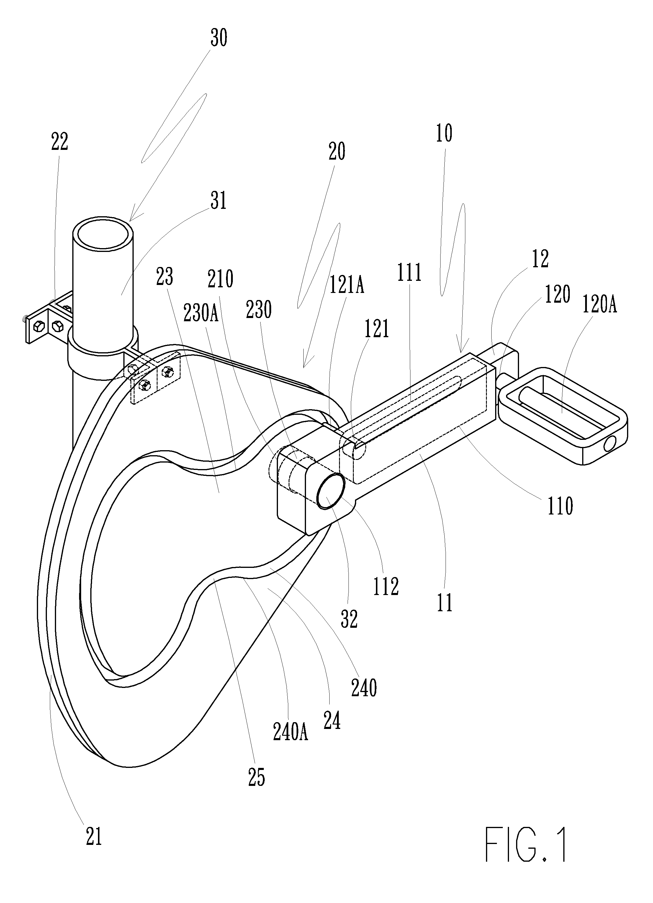
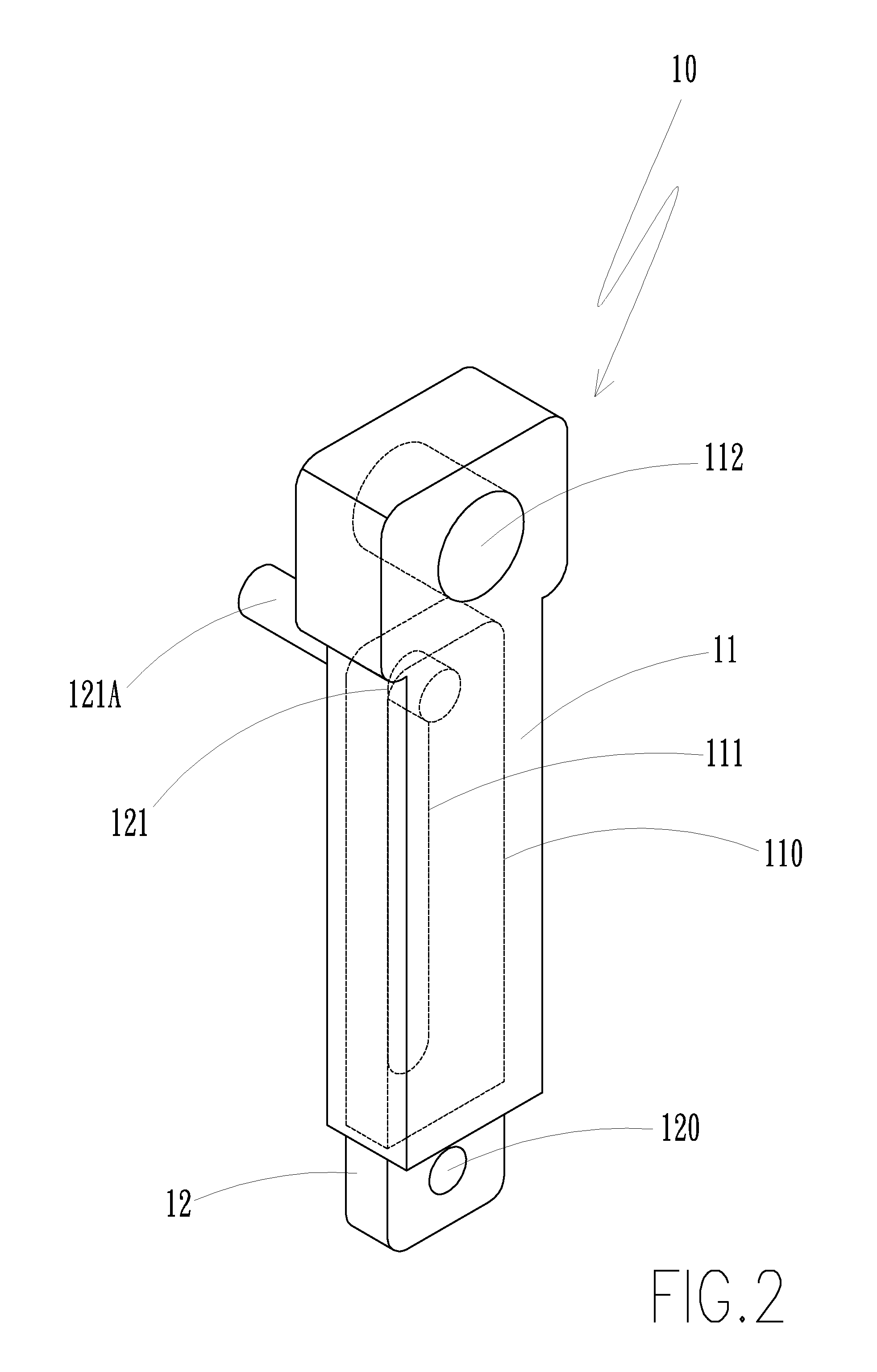
[0017]FIG. 1 is a perspective view showing an extendable crank unit and a cam unit according to a preferred embodiment of the present invention. FIG. 2 is a perspective view showing the extendable crank unit according to the preferred embodiment of the present invention. FIG. 3 is an exploded view showing an immovable crank and a movable crank according to the preferred embodiment of the present invention. FIG. 4 is a schematic view showing the extendable crank unit, the cam unit and a bike frame according to the preferred embodiment of the present invention. The present invention comprises at least one extendable crank unit (10), at least one cam unit (20) and a bike frame (30).

[0018]The extendable crank unit (10) comprises an immovable crank (11) and a movable crank (12). The immovable crank (11) has a slide trough (110) therein, a limit groove (111...


PUM


Abstract

A bike extendable crank includes an extendable crank unit. The extendable crank unit includes an immovable crank and a movable crank. The immovable crank has a slide trough therein, a limit groove at one side thereof and a main axle hole above the limit groove. One end of the movable crank has a first pivot hole for connection of a pedal and another end of the movable crank has a second pivot hole for connection a guide axle. The movable crank is slidably received in the slide trough of the immovable crank. The guide axle inserting through the second pivot hole of the movable crank slides in the limit groove of the immovable crank.

Description

BACKGROUND OF THE INVENTION[0001]1. Field of the Invention[0002]The present invention relates to a bike extendable crank, and more particularly, to a bike extendable crank which is labor-saving to drive the bike.[0003]2. Description of the Prior Art[0004]The length of a conventional bike crank is immovable. For saving labor, the length of the crank can be lengthened. But, the rotation speed becomes slow because the circumference diameter is increased. If there is a bump on the road, the crank may collide with the bump to cause an accident. For a high-speed rotation, the crank can be shortened to reduce the circumference diameter. However, it is laborious. A long crank can save labor, but the rotation speed is low. A short crank can provide a high-speed rotation, but it is laborious. Accordingly, the inventor of the present invention has devoted himself based on his many years of practical experiences to solve these problems.SUMMARY OF THE INVENTION[0005]The primary object of the pre...

Claims


Application Information

Patent Timeline
IPC IPC(8): B62M3/02
CPCB62M3/04Y10T74/2164
Inventor CHANG, SHUN-JIE
Owner CHANG SHUN JIE
Why Eureka
Try Eureka