Clamping device

a technology of clamping device and sleeve, which is applied in the direction of magnetic bodies, electrical appliances, manufacturing tools, etc., can solve the problems of limiting its practicality and usefulness, not being able to securely support itself in an upright position, and being particularly undesirabl

Active Publication Date: 2014-03-13
ROMAN COMPANY USA
View PDF9 Cites 8 Cited by
  • Summary
  • Abstract
  • Description
  • Claims
  • Application Information

AI Technical Summary

Benefits of technology

[0014]According to one embodiment of the present disclosure, there is provided a clamping device for magnetically clamping non-magnetic material objects which comprises a first clamp member having at least a first straight edge surface, the first clamp member having at least a first magnet disposed therein; a second clamp member having at least a second straight edge surface, the second clamp member having at least a second magnet disposed therein; wherein the first straight edge surface of the first clamp member and the second straight edge surface of the second clamp member are adapted to magnetically and removably couple the first and second clamp members, wherein the magnetic coupling is capable of clamping a non-magnetic material object in between the first and second straight edge surfaces; and a support member for securely positioning the clamping device on an underlying substantially level surface.

Problems solved by technology

However, the prior clamping device has a number of shortcomings and disadvantages that limit its practicality and usefulness.
Because of the narrow design of the prior art clamping device (i.e., the outer clamping member) it does not securely support itself in an upright position when placed on a work surface but will tip on its side unless held in place by the modeler.
This is particularly undesirable when model pieces to be assembled are positioned on the clamping device.
Furthermore, the outer and inner clamp members of the prior clamping device are made of an opaque material, which limits the modeler's view of the model pieces clamped in the device during assembly.
In addition, the inner clamp member of the prior clamping device has no openings that would allow a modeler to insert, for example, an applicator for adhesives.
Another substantial shortcoming of the prior clamping device is its lack of any visual or tactile markings indicating the correct alignment of the outer and the inner clamp members with regard to the respective polarity of the magnets disposed therein, an issue necessitated by the basic principle that unlike magnetic poles attract, while like magnetic poles repel each other.
This is a problem because the modeler must rely on trial and error to correctly align the clamping members so that the bringing together of unlike magnetic poles result in an attraction, i.e., coupling of the two clamp members.
An incorrect alignment of the clamp members, i.e., bringing together like magnetic poles, would result in their repelling each other.
The repelling forces may cause unwanted shifting of the clamping device itself and / or any material pieces located on it.

Method used


Image

  • Clamping device
  • Clamping device
  • Clamping device

Examples


Embodiment Construction

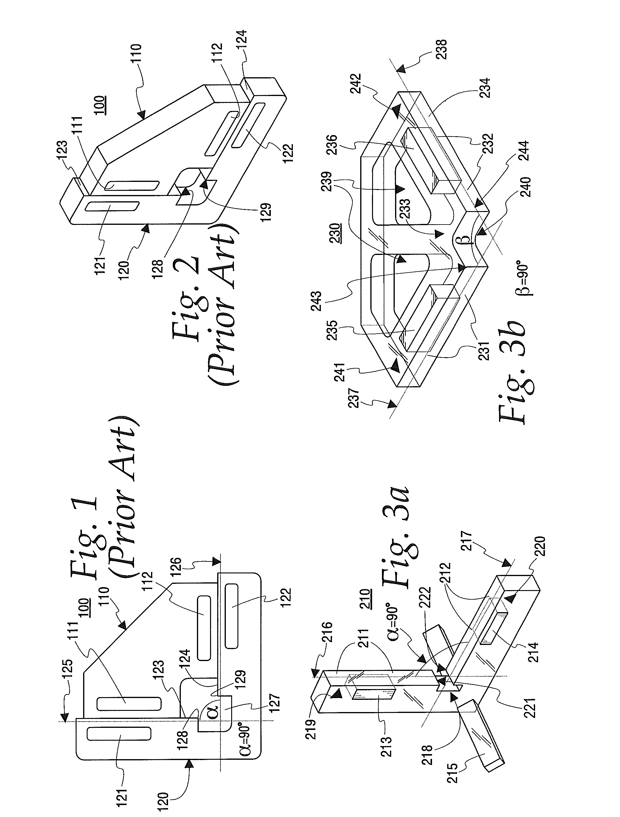
[0028]Turning to the Figures and to FIGS. 1 and 2 in particular, the prior art clamping device 100 is shown. In particular, the prior clamping device 100 comprises two clamp members, i.e., an inner clamp member 110 and an outer clamp member 120. Each of the clamp members 110 and 120 is made of an opaque material (i.e., opaque plastic). Inner clamp member 110 also comprises magnets 111 and 112 and outer clamp member 120 comprises magnets 121 and 122. Outer clamp member 120 is L-shaped and comprises two interior straight edge surfaces 123 and 124 along their respective longitudinal axes 125 and 126 which are perpendicular (i.e., 90 degree angle) to each other. Straight edge surface 123 terminates into recess 127 at surface step 128. Straight edge surface 124 terminates into recess 127 at surface step 129. Inner clamp member 110 further comprises two exterior straight edge surfaces (not shown) also along their respective longitudinal axes which are perpendicular to each other. As illus...


PUM


Abstract

A clamping device for magnetically clamping non-magnetic material objects. The clamping device comprises first and second clamp members each having at least one straight edge surface and each having at least one magnet disposed therein. The first and second clamp members are adapted to magnetically and removably couple to each other, wherein the magnetic coupling is capable of clamping at least one non-magnetic material object. The clamping device is further at least partially transparent, includes markings to facilitate correct alignment of the clamp members and comprises a support member for securely positioning the clamping device on an underlying surface.

Description

CROSS-REFERENCE TO RELATED APPLICATIONS[0001]None.TECHNICAL FIELD[0002]This application relates to tools and devices that aid in the assembly of certain material structures and in particular to a clamping device for magnetically clamping non-magnetic material objects. One particular possible use of the disclosed clamping device is as a model building tool to facilitate the assembly of model train structures (e.g., scale buildings) or the like by temporarily holding in place model pieces during model assembly.BACKGROUND OF THE DISCLOSURE[0003]Subject of this disclosure are certain improvements over a prior clamping device. In particular, the prior clamping device comprises two clamp members, i.e., an inner and an outer clamp member. Each of the clamp members is made of an opaque material and each further comprises two magnets. The outer clamp member is L-shaped and comprises two interior straight edge surfaces whose respective longitudinal axes are perpendicular to each other. The in...

Claims


Application Information

Patent Timeline
Patent Type & Authority Applications(United States)
IPC IPC(8): B25B11/00
CPCB25B11/002H01F7/0252
Inventor PLASZEWSKI, REYPLASZEWSKI, ROMAN
Owner ROMAN COMPANY USA
Why Eureka
Try Eureka