Illumination light source device and projector provided with the same, and control method of the projector

a technology of illumination light source and projector, which is applied in the direction of static indicating devices, lighting and heating apparatus, instruments, etc., can solve the problems of reducing the loss of light intensity of the light emitted from the light source used for excitation of fluorescent light, and the possibility of degradation of the fluorescent property of phosphor, so as to avoid the reduction of the generation efficiency of fluorescent light and reduce the uneven brightness of ligh

Inactive Publication Date: 2014-03-13
RICOH KK
View PDF5 Cites 32 Cited by
  • Summary
  • Abstract
  • Description
  • Claims
  • Application Information

AI Technical Summary

Benefits of technology

[0016]The present invention is made in view of the circumstances described above. An object of the present invention is to provide an illumination light source device which is capable of lowering unevenness of brightness of the light used for irradiating a screen while avoiding lowering of generation efficiency of fluorescent light generated from phosphor, when light from the light source is used by being split into a light path used for exciting fluorescent light and a light path used for irradiating a screen, a projector incorporated with the illumination light source device, and a control method of the projector.

Problems solved by technology

However, due to the configuration that the excitation light is irradiated directly to the phosphor of a phosphor wheel, the irradiation time per one unit (one second) to the phosphor is fixed regardless of a rotation number of the phosphor per one unit of time (one second), so that there is still the possibility of degradation of fluorescent property of the phosphor if excitation light is continuously irradiated to a micro area of the phosphor.
However, if such a construction is simply adopted, there is a disadvantage in that the loss of light intensity of the light emitted from the light source used for excitation of the fluorescent light is large.
However, if such, the generation efficiency of the fluorescent light is reduced, as a result of which the power density of the light from the light source used for the excitation of the phosphor is too high.

Method used


Image

  • Illumination light source device and projector provided with the same, and control method of the projector
  • Illumination light source device and projector provided with the same, and control method of the projector
  • Illumination light source device and projector provided with the same, and control method of the projector

Examples


embodiment 1

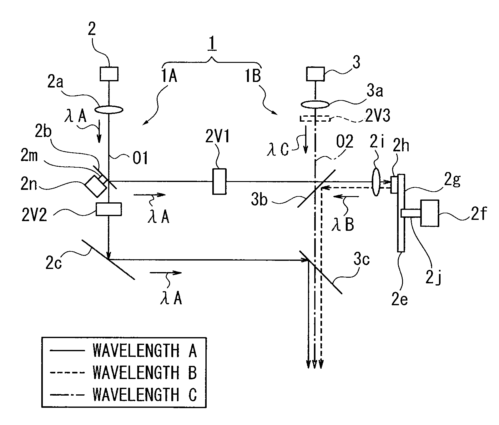
[0036]FIG. 1 illustrates a first embodiment of an illumination light source device according to the present invention. In FIG. 1, numeral 1 shows an illumination optical system.

Construction of Illumination Optical System 1

[0037]The Illumination optical system 1 has two illumination light sources (hereinafter, referred to as light sources) 2 and 3 in the illustrated embodiment. The light source 2 (excitation light source) is included in a first illumination optical system 1A. The light source 3 is included in a second illumination optical system 1B.

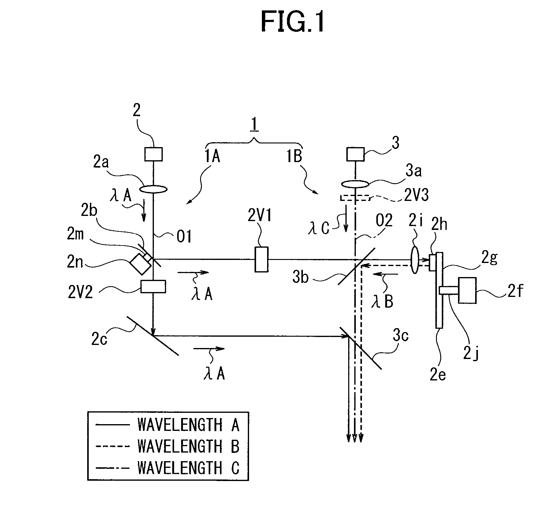
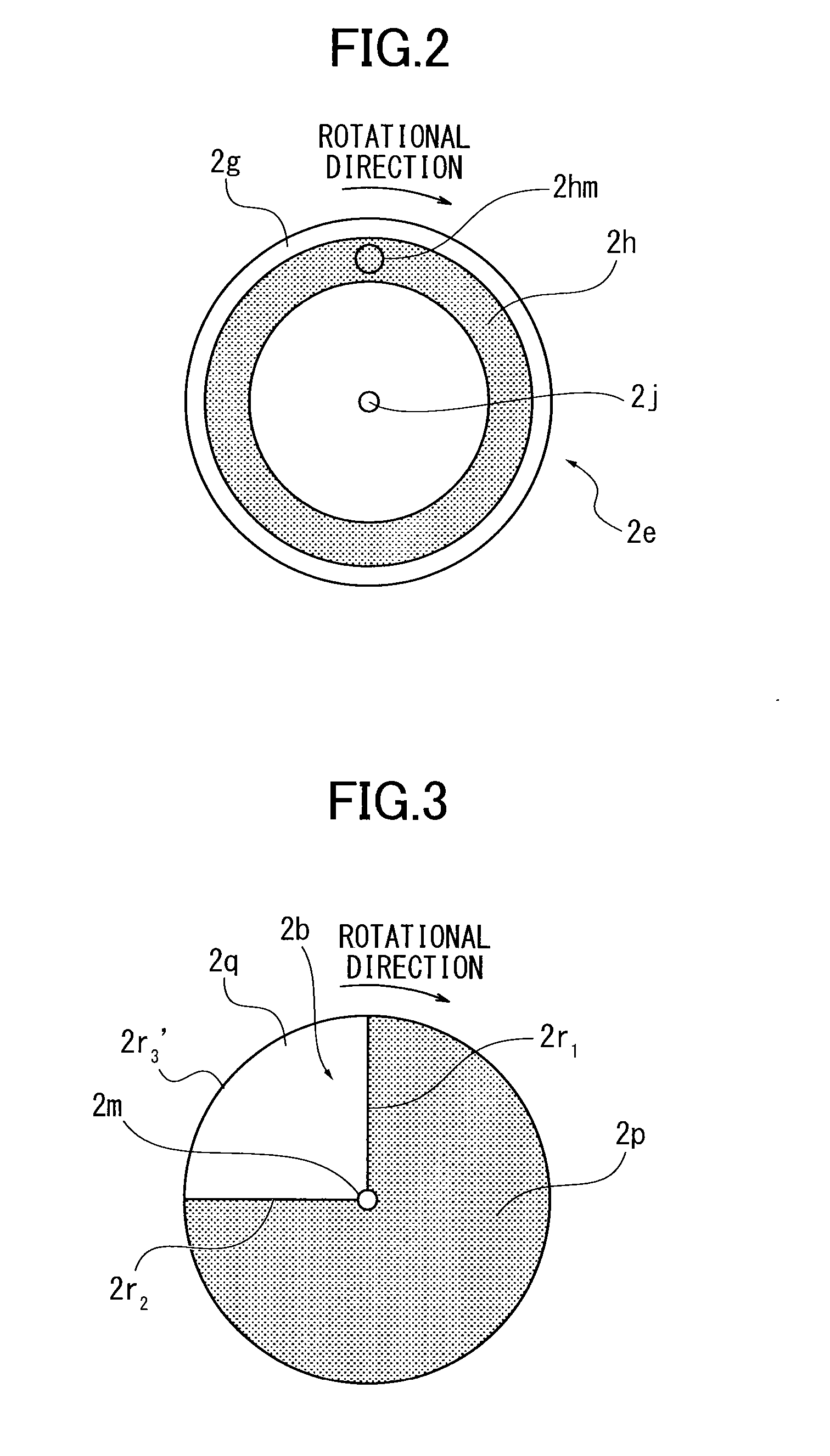
[0038]The first illumination optical system 1A schematically includes a coupling lens 2a as a first optical element, a reflection / transmission wheel 2b as a reflecting / transmitting member, a total reflection mirror 2c and a phosphor wheel 2e as a phosphor member. Herein, numeral 01 shows an optical axis of the first illumination optical system 1A.

[0039]The reflection / transmission wheel 2b is provided in an emitting light path of the light ...

embodiment 2

[0085]FIG. 4 illustrates one example of the structure of a Projector 10 incorporating the illumination optical system 1 of Embodiment 1. In FIG. 4, the same numerals and characters as Embodiment 1 are used to represent the similar constituent, and the detailed description thereof is omitted here.

[0086]The projector 10 includes a controller 11 which controls the illumination optical system 1, a light-condensing element 12, an integrator 13, a light-condensing element 14, a reflection mirror 15, an image generator 16 and a projection lens 17. The light-condensing element 12, the integrator 13, the light-condensing element 14 and the reflection mirror 15 are included in an irradiating optical system which directs the illumination light emitted from the dichroic mirror 3c to the image generator 16. The projection lens 17 is included in a projection light system which projects a projection image generated by the image generator. By the projection light system, the projection image is pro...

embodiment 3

[0115]FIG. 7 is an optical view showing an illumination light source device according to Embodiment 3 of the present invention. FIG. 8A and FIG. 8B are explanatory views of the diffusion of the illumination light of the illumination light source device shown in FIG. 7. FIG. 8A shows the diffusion condition of the light when the transmission / diffuser plate is disposed only one in the light path where the light from the first illumination optical system 1A does not pass through the phosphor wheel. FIG. 8B shows the diffusion condition of light from the first illumination optical system when two transmission / diffuser plates are disposed in the light path where the light from the first illumination optical system 1A does not pass through the phosphor wheel.

[0116]In Embodiment 3, as shown in FIG. 7, another transmission / diffuser plate 2v2′ different from the transmission / diffuser plate 2v2 is disposed in the light path where the light of the wavelength λA from the first illumination opti...


PUM


Abstract

An illumination light source device, comprising: a light path junction member which splits light emitted from a light source into a first light path emitting excitation light for phosphor and a second light path irradiating illumination light; a first diffuser disposed in the first light path; and a second diffuser disposed in the second light path, the second diffuser having a diffusion degree larger than that of the first diffuser.

Description

CROSS-REFERENCE TO THE RELATED APPLICATIONS[0001]The present application is based on and claims priority from each of Japanese Patent Application No. 2012-198147, filed on Sep. 10, 2012, and Japanese Patent Application No. 2013-000938, filed on Jan. 8, 2013, the disclosures of which are hereby incorporated by reference in their entirety.BACKGROUND OF THE INVENTION[0002]1. Field of the Invention[0003]The present invention relates to an improvement of an illumination light source device and a projector provided with the illumination light source device, and a control method of the projector.[0004]2. Description of the Related Art[0005]For instance, for use at a conference and so on, an illumination light source device for a projector for projecting screen information of a personal computer (hereinafter referred to as “PC”) and so on, which has a high luminance discharge lamp (for instance, a super high-pressure mercury lamp) as a light source, is known.[0006]The discharge lamp provide...

Claims


Application Information

Patent Timeline
Patent Type & Authority Applications(United States)
IPC IPC(8): G03B21/20F21V9/08
CPCF21V9/08G03B21/204G02B27/10G03B21/2066G03B33/08
Inventor TAKAHASHI, TATSUYAFUJITA, KAZUHIRO
Owner RICOH KK
Why Eureka
Try Eureka