Prosthetic heart valve

a heart valve and prosthesis technology, applied in the field of prosthetic heart valves, can solve the problems of affecting the function of the heart, and being less efficient in some respects, and being more thrombogenic than previous mechanical prosthetic valves

Inactive Publication Date: 2014-03-13
NEGRI JUSTIN
View PDF27 Cites 1 Cited by
  • Summary
  • Abstract
  • Description
  • Claims
  • Application Information

AI Technical Summary

Benefits of technology

[0013]According to preferred embodiments, each leaflet bends through first and second bends as the leaflet extends toward a tip of the leaflet. Preferably, the first bend extends in a direction which is upstream when the valve is in a closed position and the second bend extends in a direction which is downstream when the valve is in a closed position. Preferably, the first bend is in the form of a curve having an axis which is between 2 mm and 10 mm from an axis of rotation of the leaflet, and more preferably between 4 mm and 7 mm.
[0014]Preferably, the second bend is in the form of a curve having an axis which is approximately 4 mm from a tip of the leaflet. Preferably, a height of either of the first or second bends is between 0.5 mm and 1.8 mm from a longitudinal axis of the leaflet, and more preferably between 0.85 mm and 1.45 mm.

Problems solved by technology

Although previous biological prosthetic valves provide performance which is comparable to that of a natural human valve, biological valves generally have a limited service life and may require replacement after 10 to 15 years of use.
However, previous mechanical prosthetic valves have typically been less efficient in some respects and more thrombogenic than biologic valves.
Furthermore, the geometry of previous mechanical valves used for mitral valve replacement, having a circular and planar annulus and having substantially planar leaflets, is different from the natural contour of the mitral annulus in which it is to be received, resulting in a sub-optimal fit of the valve in the annulus which affects the natural blood hemodynamics through and around the valve.
Due to the sub-optimal fit, the Tendinous cords and Papillary muscles of the heart require deformation to accept the prosthetic valve and this deformation mimics some disease states and has the potential to impact negatively on function of the heart.
Also, previous mechanical valves having a substantially planar geometry do not take advantage of the available cross sectional of the mitral annulus, thereby creating a flow restriction so that natural flow is impeded, thereby reducing potential performance of the valve compared with a normally functioning natural valve.
Previous mechanical valves can also generate a notable acoustic disturbance that can be heard by the patient.
Although annuloplasty rings assist the natural function of the heart, they do not address issues arising from damaged leaflets and thus are not useful when a complete mitral valve replacement is required.

Method used


Image

  • Prosthetic heart valve
  • Prosthetic heart valve
  • Prosthetic heart valve

Examples


Embodiment Construction

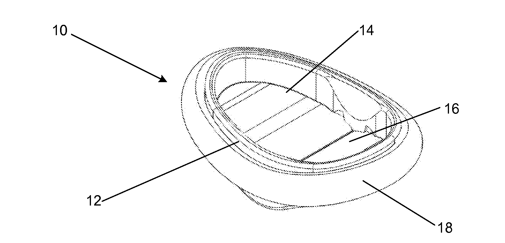
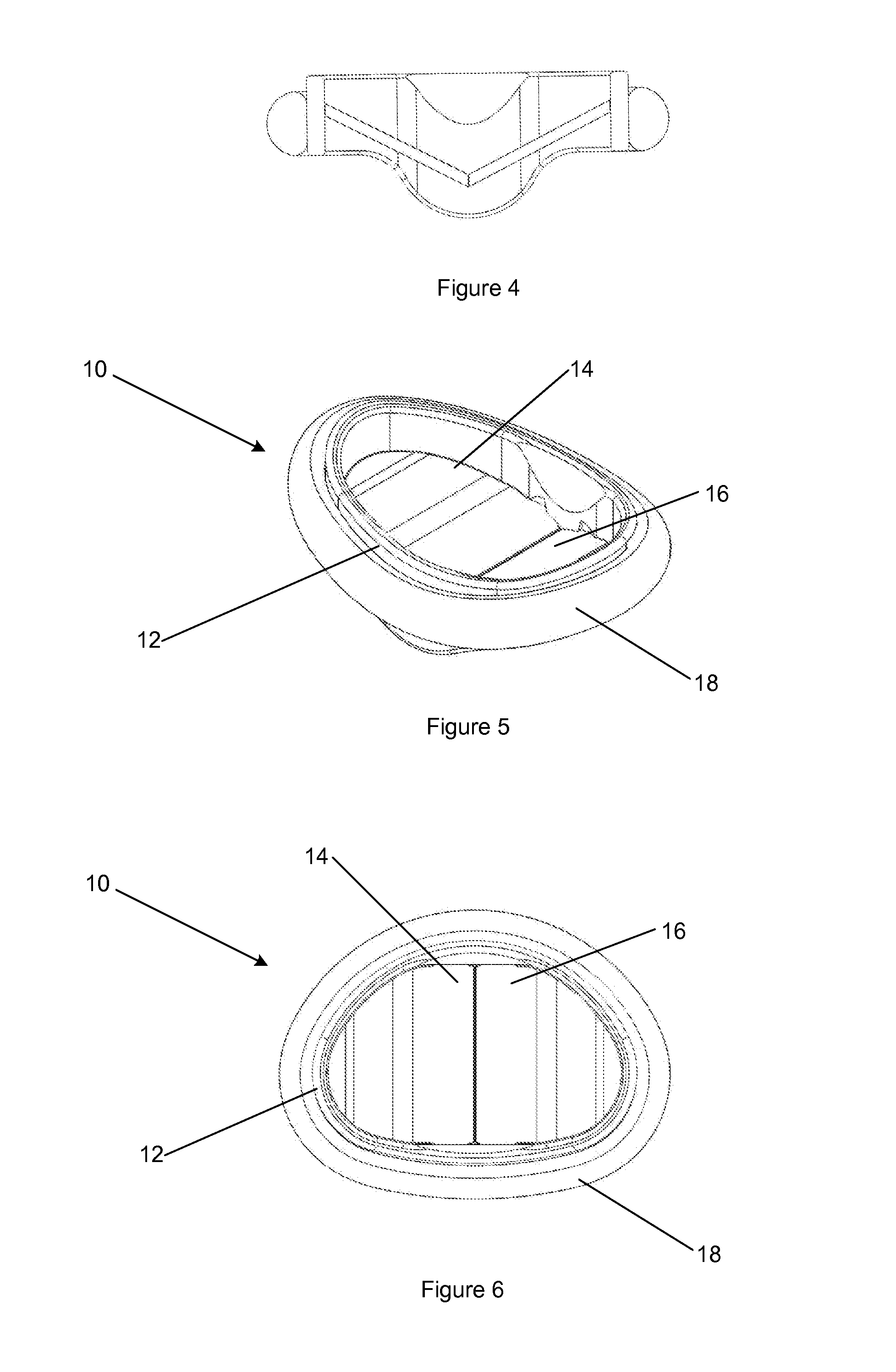
[0029]A valve assembly 10 according to a preferred embodiment of the present invention is shown in FIG. 5. The valve assembly 10 is configured for use as a prosthetic mitral valve in a human heart.

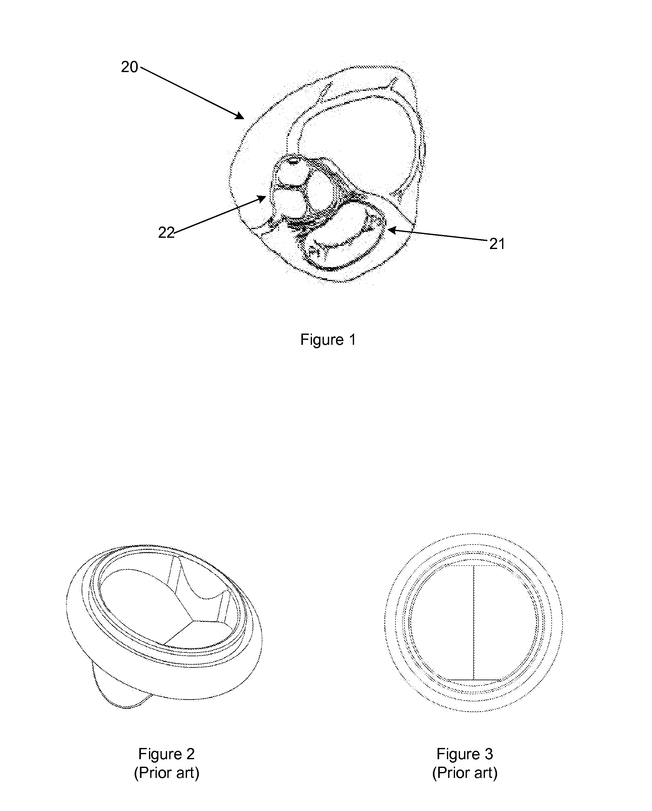
[0030]The valve assembly 10 includes a housing 12 in which a plurality of leaflets 14, 16 are pivotally supported. In the described embodiment a pair of like leaflets 14, 16 are provided, although it is envisaged that arrangements having 3 or more leaflets may similarly be provided. In the described embodiment, each leaflet is rigid or substantially rigid and arranged to be symmetrical about a central plane disposed between the leaflets. A periphery of the leaflets 14, 16 cooperates with an inner surface of the housing 12 to close the valve 10. The housing 12 is formed with an external shape which substantially corresponds to that of the mitral annulus 21 (see FIG. 1) so as to fit within the annulus.

[0031]As illustrated in FIGS. 5 and 6, though removed from FIGS. 7 and 8 for clarity, the a...


PUM


Abstract

A prosthetic mitral valve assembly, comprising a housing in which a plurality of leaflets are pivotally supported, wherein a periphery of the leaflets cooperates with an inner surface of the housing to close the valve and the housing is formed with an external shape which substantially corresponds to that of a mitral valve annulus so as to fit within the annulus.

Description

FIELD OF THE INVENTION[0001]The present invention relates to a prosthetic heart valve. More particularly, but not exclusively, the present invention relates to a prosthetic mitral valve for use in a human heart.BACKGROUND OF THE INVENTION[0002]Biological and mechanical prostheses have been previously proposed for use as replacement heart valves. Although previous biological prosthetic valves provide performance which is comparable to that of a natural human valve, biological valves generally have a limited service life and may require replacement after 10 to 15 years of use.[0003]Previous mechanical prosthetic valves have been found to have a service life far exceeding that of biological valves. However, previous mechanical prosthetic valves have typically been less efficient in some respects and more thrombogenic than biologic valves.[0004]Furthermore, the geometry of previous mechanical valves used for mitral valve replacement, having a circular and planar annulus and having subst...

Claims


Application Information

Patent Timeline
Patent Type & Authority Applications(United States)
IPC IPC(8): A61F2/24
CPCA61F2/2412A61F2/2403A61F2/2409A61F2250/0036
Inventor NEGRI, JUSTINHUSBAND, DAVID
Owner NEGRI JUSTIN
Why Eureka
Try Eureka