Methods and apparatus for coupling an allograft tissue valve and graft

a tissue valve and allograft technology, applied in the field of allograft tissue valve and graft coupling, can solve the problems of coagulant cascade, more common valve failure, damage to blood elements,

Inactive Publication Date: 2006-04-20
MEDTRONIC INC
View PDF20 Cites 330 Cited by
  • Summary
  • Abstract
  • Description
  • Claims
  • Application Information

AI Technical Summary

Benefits of technology

[0020] In accordance with the present invention, methods and apparatus are provided for use during a valve replacement procedure for rapidly and securely attaching a prosthetic heart valve to a vascular graft. In accordance with one aspect of the present inven

Problems solved by technology

Prosthetic heart valves can be used to replace any of these naturally occurring valves, although repair or replacement of the aortic or mitral valves is most common because they reside in the left heart chambers where the pressure loads are higher and valve failure is more common.
The opening and closing of mechanical valve occluders can damage blood elements and trigger a coagulant cascade.
However, tissue leaflets can become calcified over time distorting the leaflet shape and ultimately leading to failure of the tissue leaflets to fully close or open.
However, calcification and tear issues of polymeric materials remain to be solved before a polymeric mechanical valve mimicking the function of the leaflets of a tissue valve can be realized.
Sewing a graft onto the prosthetic heart valve sewing ring in this manner can be a chalenge, resulting in the possibility of blood leakage through or between the sutured end of the graft and the sewing ring.
In addition, the procedure may take an unduly long time, which can cause complications for a patient on cardiac bypass.
Moreover, blood leakage through the suture holes typically occurs until the blood coagulates in the holes, and such blood loss is undesirable.
Furthermore, the tapered design and fabrication of the graft created problems that made anastomosis of the free ends of the coronary arteries to the sidewall of the graft difficult.
The reduced diameter and method of fabrication of

Method used


Image

  • Methods and apparatus for coupling an allograft tissue valve and graft
  • Methods and apparatus for coupling an allograft tissue valve and graft
  • Methods and apparatus for coupling an allograft tissue valve and graft

Examples


Embodiment Construction

[0053] In the following detailed description, references are made to illustrative embodiments of methods and apparatus for carrying out the invention. It is understood that other embodiments can be utilized without departing from the scope of the invention. Preferred methods and apparatus are described for rapidly and securely coupling a tissue valve or a mechanical valve with a graft during the replacement of a native heart valve and portion of the aorta in a heart. It will be understood that the coupling methods and compression rings that are depicted in the drawings in relation to either a tissue valve or a mechanical valve may be used for both tissue and mechanical valves unless otherwise explicitly stated. The particular manner of fabrication of the individual components of the tissue valves and mechanical valves are not of importance to the present invention.

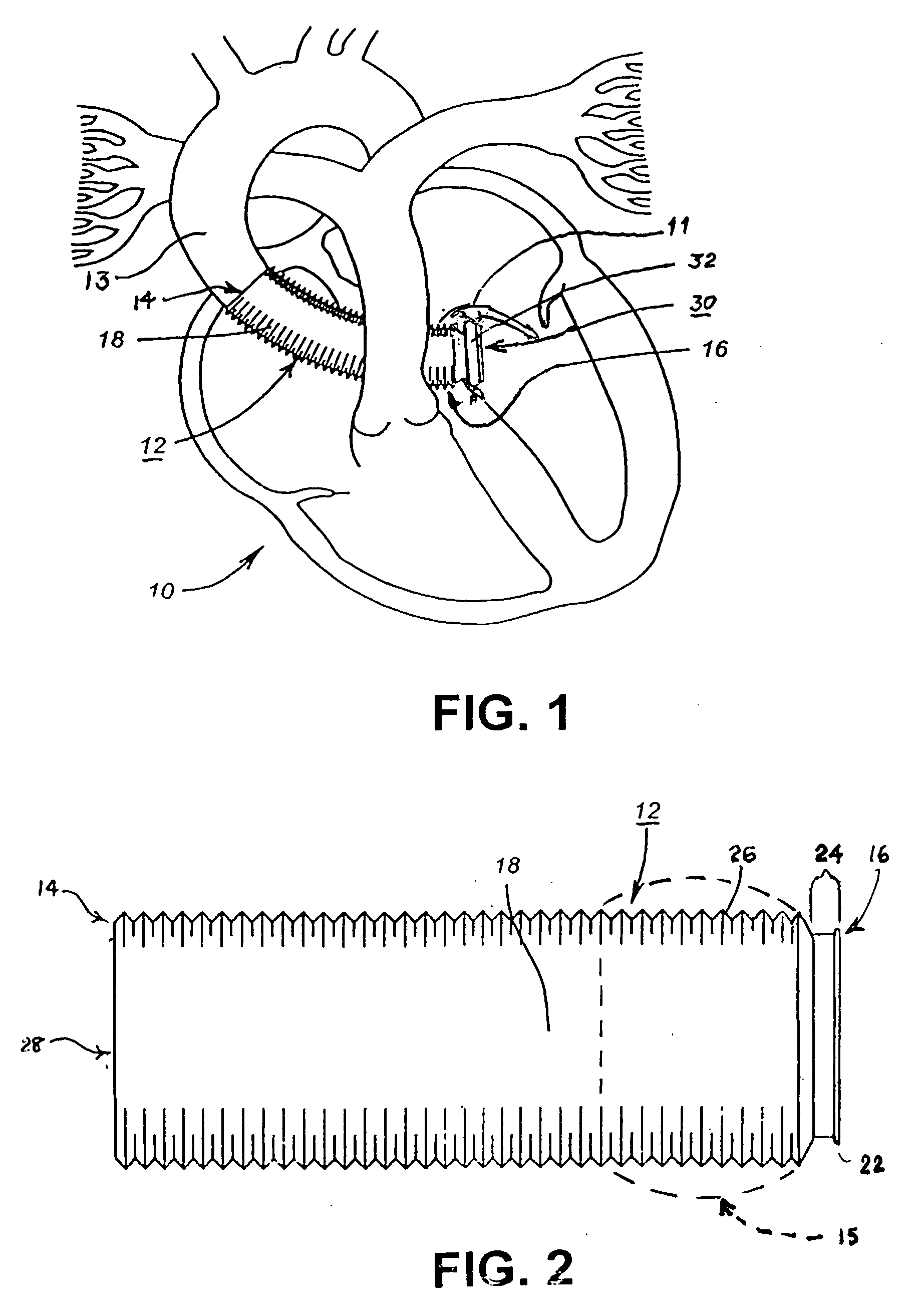
[0054]FIG. 1, similar to FIG. 1 of the above-referenced '195 patent, is a partial cross-section, schematic view of a hu...


PUM


Abstract

Improvements to prosthetic heart valves and grafts for human implantation, particularly to methods and apparatus for coupling a prosthetic heart valve with an artificial graft during a surgical procedure to replace a defective heart valve and blood vessel section, e.g., the aortic valve and a section of the ascending aorta, are disclosed. An annular exterior surface of the prosthetic heart valve is fitted within a vascular graft lumen to dispose the vascular graft proximal end overlying the annular exterior surface, and the proximal end of an elongated vascular graft is compressed against the valve annular exterior surface in a manner that inhibits blood leakage between the vascular graft and the prosthetic heart valve.

Description

FIELD OF THE INVENTION [0001] This invention relates to improvements to prosthetic heart valves and grafts for human implantation, particularly to methods and apparatus for coupling a prosthetic heart valve with an artificial graft during a surgical procedure to replace a defective heart valve and blood vessel section, e.g., the aortic valve and a section of the ascending aorta. BACKGROUND OF THE INVENTION [0002] Implantable heart valve prostheses or prosthetic heart valves have been used to replace various diseased or damaged native aortic valves, mitral valves, pulmonic valves and tricuspid valves of the heart. Heart valves are most frequently replaced due to heart disease, congenital defects or infection. The aortic valve controls the blood flow from the left ventricle into the aorta, and the mitral valve controls the flow of blood between the left atrium and the left ventricle. The pulmonary valve controls the blood flow from the right ventricle into the pulmonary artery, and th...

Claims


Application Information

Patent Timeline
IPC IPC(8): A61F2/06A61F2/24
CPCA61F2/06A61F2/2412
Inventor CAMPBELL, LOUIS A.
Owner MEDTRONIC INC
Why Eureka
Try Eureka