Electromagnetic relay

a technology of electromagnetic relays and relays, applied in electromagnetic relay details, contact vibration/shock damping, electrical apparatus, etc., can solve the problem of large collision energy generated between fixed contacts, and achieve the effect of suppressing collision energy and contact pressur

Inactive Publication Date: 2014-04-03
NISSAN MOTOR CO LTD
View PDF3 Cites 17 Cited by
  • Summary
  • Abstract
  • Description
  • Claims
  • Application Information

AI Technical Summary

Benefits of technology

[0007]According to the present invention, when the movable contact and the fixed contact are brought into contact, the contact pressure between fixed contact and the movable contact is reduced, and after the fixe

Problems solved by technology

However, there is a problem that the collision energy generated between the fixed c

Method used


Image

  • Electromagnetic relay
  • Electromagnetic relay
  • Electromagnetic relay

Examples


Embodiment Construction

[0015]Hereinafter, description is given of an embodiment according to the present invention with reference to the drawings.

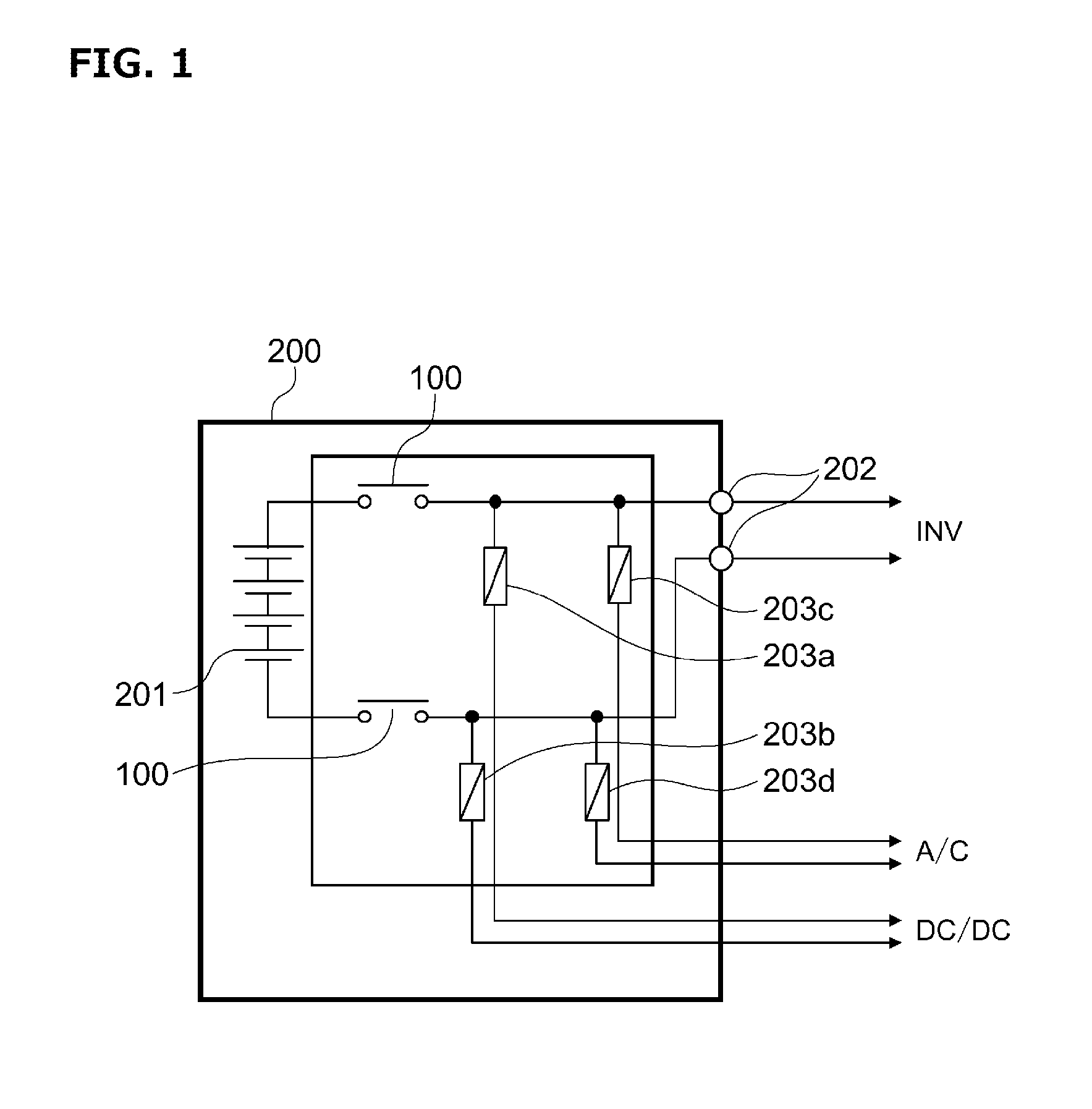
[0016]FIG. 1 is a block diagram illustrating a battery pack of a vehicle including an electromagnetic relay (hereinafter referred to as a relay switch) in an exemplary embodiment according to the present invention. For example, the relay switch 100 is used as a main relay for electric vehicles or hybrid vehicles. The relay switch 10 may be applied to other switches for the vehicle or even be applied to a switch used as ones for the purpose other than vehicle.

[0017]As shown in FIG. 1, the battery pack 200 includes a battery 201, a relay switch 100, a connector portion 202, and fuses 203a˜203d. The battery 201 a drive source for driving the vehicle and is formed by connecting batteries such as secondary batteries or the like in series or in parallel. A relay switch 100 is respectively connected to a power supply line of the positive electrode side and the power su...


PUM


Abstract

The present invention is provided with a fixed contact; a movable contact which selectively contacts with or separates from the fixed contact; and a drive means which has at least an electromagnetic coil and drives the movable contact so that the movable contact comes into contact with the fixed contact. The drive means generates a first driving force for bringing the movable contact into contact with the fixed contact, and a second driving force larger than the first driving force for maintaining the contact state between the movable contact and the fixed contact.

Description

CROSS REFERENCE TO RELATED APPLICATION[0001]The present application claims priority to Japanese Patent Application No. 2011-136151 filed on Jun. 20, 2011, which is incorporated herein in its entirety.TECHNICAL FIELD[0002]The present invention relates to an electromagnetic relay.BACKGROUND[0003]A starter solenoid switch such as that in JP Patent Publication No. 2004-207134 is provided with a plunger that is inserted into the inner diameter side of an exciting coil and opposes a fixed core with an air gap, a spring biasing the plunger in an anti-core direction, a fixed contact movable integrally with the plunger and, when sucked to the fixed core side upon energizing the exciting coil, comes into contact with the fixed contact to close a current supply circuit, and an elastic member mounted in the plunger to protrude toward a stopper surface side from an end surface of the plunger located on the anti-core side. When the plunger is sucked in the fixed core side and, due to disappearanc...

Claims


Application Information

Patent Timeline
IPC IPC(8): H01H50/44
CPCH01H50/44H01H3/60H01H47/04H01H47/22H01H50/16
Inventor SORA, YOSUKE
Owner NISSAN MOTOR CO LTD
Why Eureka
Try Eureka