Optical cross-connect assembly and method

a technology of optical cross-connects and connectors, applied in the field of optical communication, can solve the problems of difficult to provide enough ports on each box to accommodate these interconnections, and it is not feasible to use pcb solutions to optically

Active Publication Date: 2014-04-03
AVAGO TECH INT SALES PTE LTD
View PDF0 Cites 24 Cited by
  • Summary
  • Abstract
  • Description
  • Claims
  • Application Information

AI Technical Summary

Benefits of technology

[0007]The invention is directed to an optical cross-connect assembly and method. The optical cross-connect assembly comprises first and second stacks of first and second multi-optical fiber connector modules, respectively. Each of the first connector modules includes a first module housing in which ends of a plurality of first optical fibers are held in fixed positions. Each of the first module housings has a plurality of first lenses disposed in respective first openings formed in a wall of the first module housing. The first openings extend through the wall and through a front surface of the first module housing. The ends of the first optical fibers are positioned adjacent the respective openings such that light is coupled between the respective first lenses and the respective ends of the first optical fibers.

Problems solved by technology

In these types of applications, it is not feasible to use PCB solutions to optically interface the boxes with one another.
In all of these types of larger-scale applications, it can be difficult to connect each box to all of the other boxes using optical fiber cables and connectors.
Providing enough ports on each box to accommodate these interconnections can be difficult.
Also, it is difficult to drive signals, especially at high speeds (e.g., gigahertz speeds), across electrical cables that have rack-sized lengths.
Electrical cables are sometimes used within a rack to make interconnections between boxes, but it is impractical to use them over long distances due to the fact that they are bulky in size and very lossy, i.e., they waste a lot of electrical power at high speed and over long lengths.
Making a PCB with optical waveguides on it that is large enough to accommodate this many interconnections is not practical because the PCB would have to be as large as the rack or large enough to span across multiple racks.

Method used


Image

  • Optical cross-connect assembly and method
  • Optical cross-connect assembly and method
  • Optical cross-connect assembly and method

Examples


Embodiment Construction

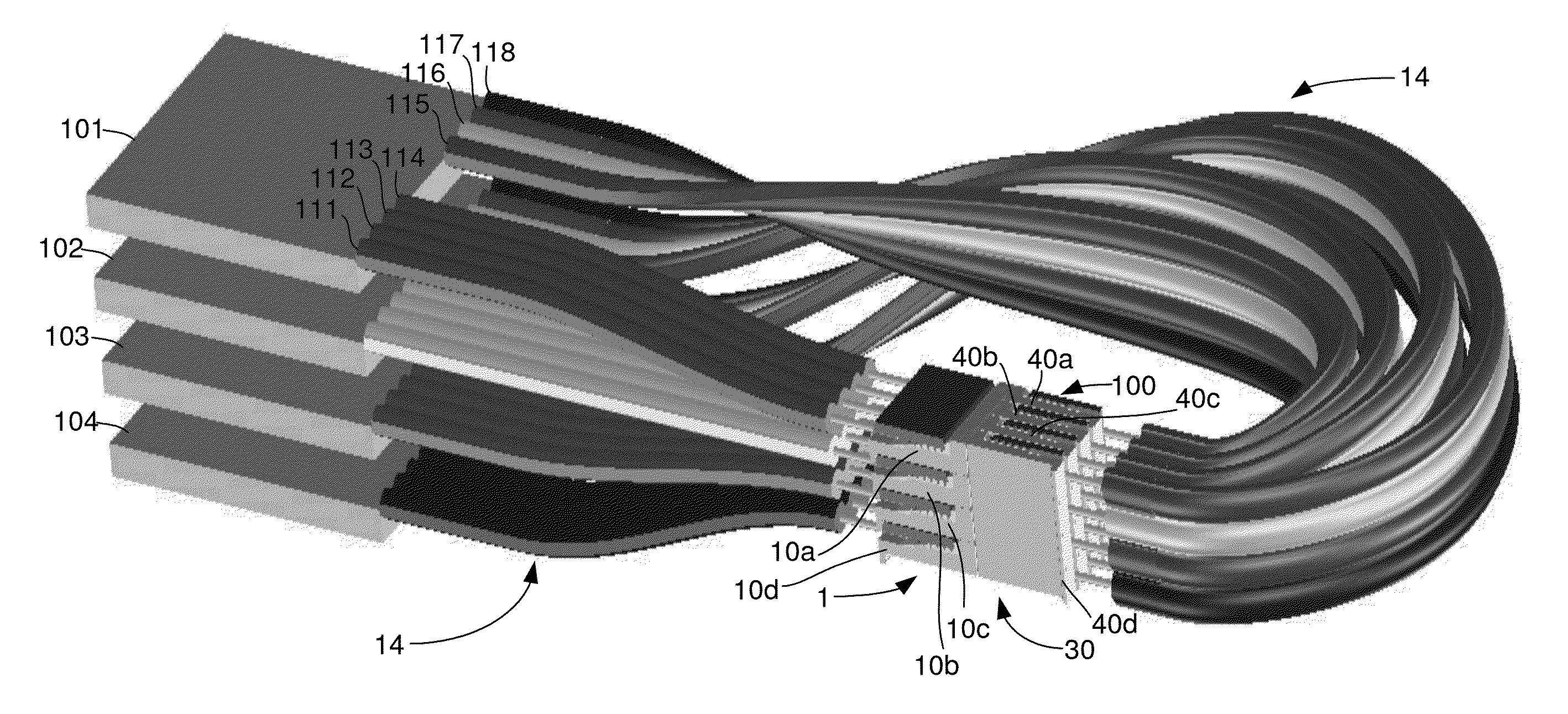
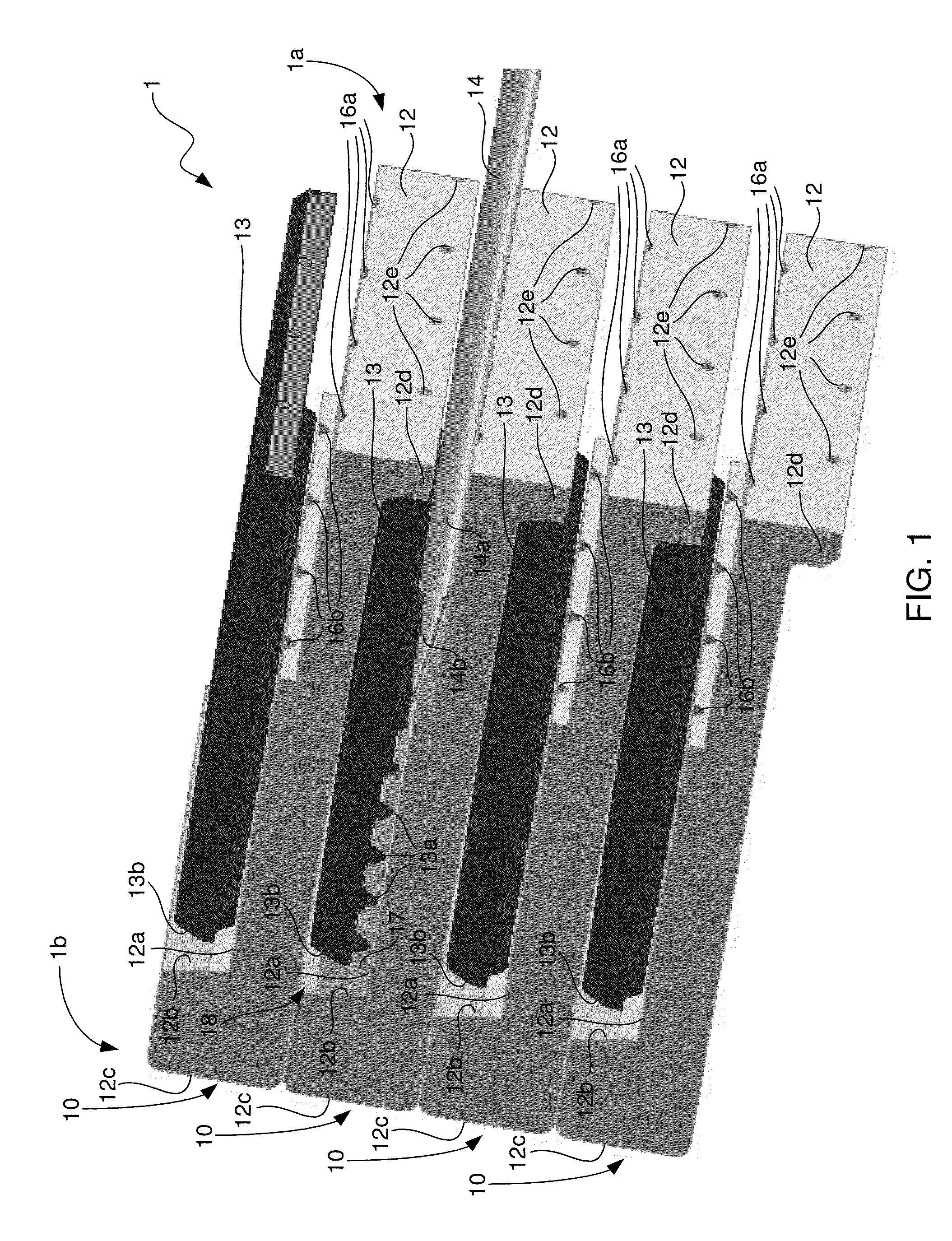
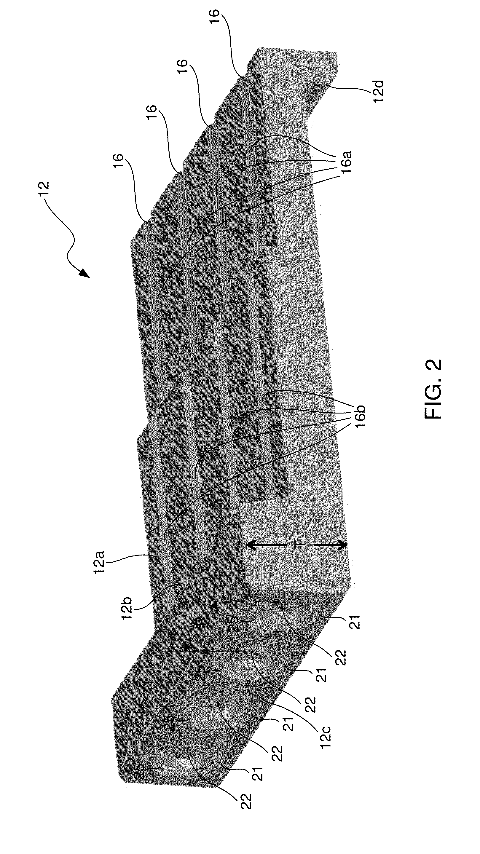
[0025]In accordance with embodiments of the invention, an optical cross-connect assembly and method are provided that are suitable for use in both small-scale and large-scale applications. The cross-connect assembly comprises first and second stacks of multi-optical fiber connector modules that are configured to orthogonally mechanically couple with one another such that the optical ports of each of the connector modules of the first stack are optically aligned with respective optical ports of all of the connector modules of the second stack, and such that the optical ports of each of the connector modules of the second stack are optically aligned with respective optical ports of all of the connector modules of the first stack. Illustrative, or exemplary, embodiments of the optical cross-connect assembly and method will now be described with reference to the figures, in which like reference numerals represent like elements, components or features. The elements, components or feature...


PUM

PropertyMeasurementUnit
shapeaaaaaaaaaa
mechanical couplingaaaaaaaaaa
mechanicalaaaaaaaaaa

Abstract

An optical cross-connect assembly and method are provided that are suitable for use in both small-scale and large-scale applications. The optical cross-connect assembly comprises first and second stacks of multi-optical fiber connector modules that are configured to orthogonally mechanically couple with one another such that the optical ports of each of the connector modules of the first stack are optically aligned with respective optical ports of all of the connector modules of the second stack, and such that the optical ports of each of the connector modules of the second stack are optically aligned with respective optical ports of all of the connector modules of the first stack.

Description

TECHNICAL FIELD OF THE INVENTION[0001]The invention relates to optical communications. More particularly, the invention relates to an optical cross-connect assembly and method for use in optical communications.BACKGROUND OF THE INVENTION[0002]An optical cross-connect assembly is an assembly that is used to interconnect optical fiber communications modules with one another. An optical fiber communications module may be an optical transceiver module having both transmit and receive optical channels, an optical transmitter module having only transmit optical channels, or an optical receiver module having only receive optical channels. An optical cross-connect assembly may be used to interconnect many such optical communications modules with many other such optical communications modules.[0003]Optical cross-connect assemblies take on a variety of forms depending on the applications in which they are used. In smaller-scale applications, printed circuit boards (PCBs) having electrical-to-...

Claims


Application Information

Patent Timeline
Patent Type & Authority Applications(United States)
IPC IPC(8): G02B6/36B23P11/00
CPCG02B6/3636G02B6/3676G02B6/3853G02B6/3855G02B6/406G02B6/43Y10T29/49826Y10T29/49908
Inventor MCCOLLOCH, LAURENCE R.FIELDS, MITCHELL H.
Owner AVAGO TECH INT SALES PTE LTD
Why Eureka
Try Eureka