Casing Projections of an Image Forming Apparatus Configured to Support a Seal of a Developing Device

a developing device and developing device technology, applied in the field of non-magnetic monocomponent developing device and image forming apparatus including developing device, can solve the problems of deteriorating sealing performance of the sealing member, and achieve the effect of favorably suppressing the leakage of toner through between both, simple and favorably performed

Active Publication Date: 2014-04-17
BROTHER KOGYO KK
View PDF0 Cites 0 Cited by
  • Summary
  • Abstract
  • Description
  • Claims
  • Application Information

AI Technical Summary

Benefits of technology

[0007]In this type of device, even if so-called “seal collapse” which greatly deforms such that the seal member collapses along the direction of the central axis of the developing roller has occurred in any direction along the direction of the central axis, the sealing performance by the seal member deteriorates. The invention has been made in order to cope with the above problems. That is, the object of the invention is to provide a non-magnetic monocomponent developing device which can suppress more effectively that a non-magnetic monocomponent developer leaks out at both ends of a roller body portion in a developing roller.
[0019]In the developing device of the invention having such a configuration, the outer projection abuts on the outer edge of the seal member in the direction of the central axis. Additionally, the inner projection abuts on the inner edge of the seal member in the direction of the central axis. Thereby, the seal member is supported between the outer projection and the inner projection which are provided on both sides of the seal member in the direction of the central axis. Accordingly, occurrence of “seal collapse” along the direction of the central axis can be effectively suppressed on both inner and outer sides in the direction of the central axis. Additionally, by inserting the seal member to between the outer projection and the inner projection, mounting of the seal member to the casing of the seal member can be easily and favorably performed.
[0020]Particularly, the outer projection and the inner projection are provided so as to face each other along the direction of the central axis, and are formed such that the lengths thereof in the movement direction become almost equal to each other. Thereby, occurrence of “seal collapse” along the direction of the central axis can be more effectively suppressed on both inner and outer sides in the direction of the central axis.
[0021]Additionally, the seal member is provided with the protruding portion, and the protruding-side abutting portion, the inner abutting portion, and the terminating abutting portion are provided on the inner projection in correspondence with the protruding portion. Thereby, the edge of the inner projection which abuts on the seal member is formed in the shape of a crank. This can effectively suppress that the developer leaks out to the outside through a slight gap formed along the abutting portion between the seal member and the inner projection. Particularly, as the leak developer storage unit is formed, the leak of the developer as described above can be more effectively suppressed.
[0022]Additionally, mounting of the seal member to the casing can be easily and favorably performed by making the upstream edge of the seal member in the movement direction abut on the upstream abutting projection when the seal member is mounted to the casing.
[0023]Additionally, in a case where the protruding height of the inner projection is made lower than the protruding height of the outer projection, a force which pushes the seal member against the inner projection can be generated while favorably suppressing occurrence “seal collapse” along the direction of the central axis. Thereby, the seal member adheres to the inner projection well. Hence, the sealing performance of the developer by the seal member improves further.

Problems solved by technology

In this type of device, even if so-called “seal collapse” which greatly deforms such that the seal member collapses along the direction of the central axis of the developing roller has occurred in any direction along the direction of the central axis, the sealing performance by the seal member deteriorates.

Method used


Image

  • Casing Projections of an Image Forming Apparatus Configured to Support a Seal of a Developing Device
  • Casing Projections of an Image Forming Apparatus Configured to Support a Seal of a Developing Device
  • Casing Projections of an Image Forming Apparatus Configured to Support a Seal of a Developing Device

Examples


Embodiment Construction

[0033]Hereinafter, embodiments of the invention will be described with reference to the accompanying drawings.

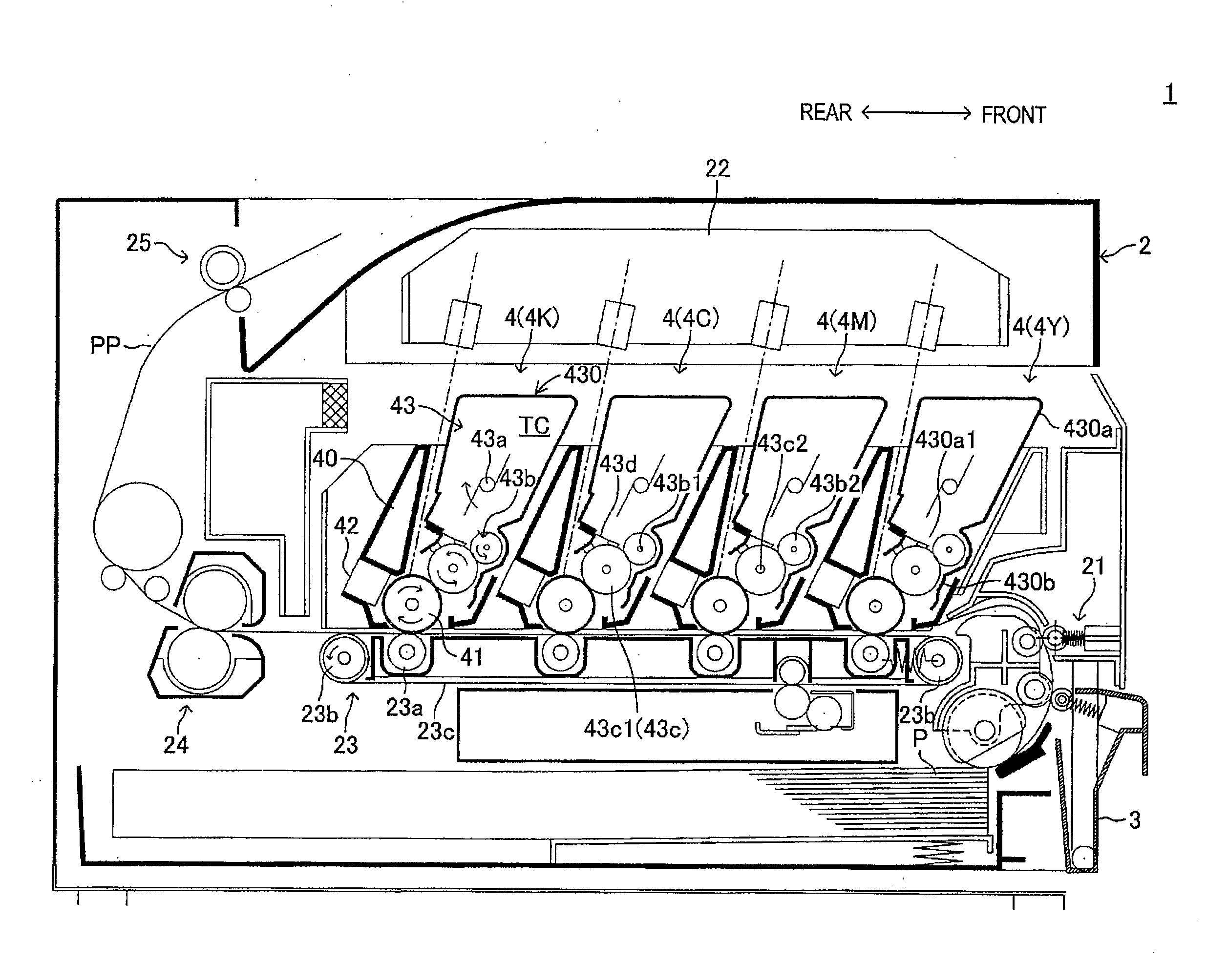
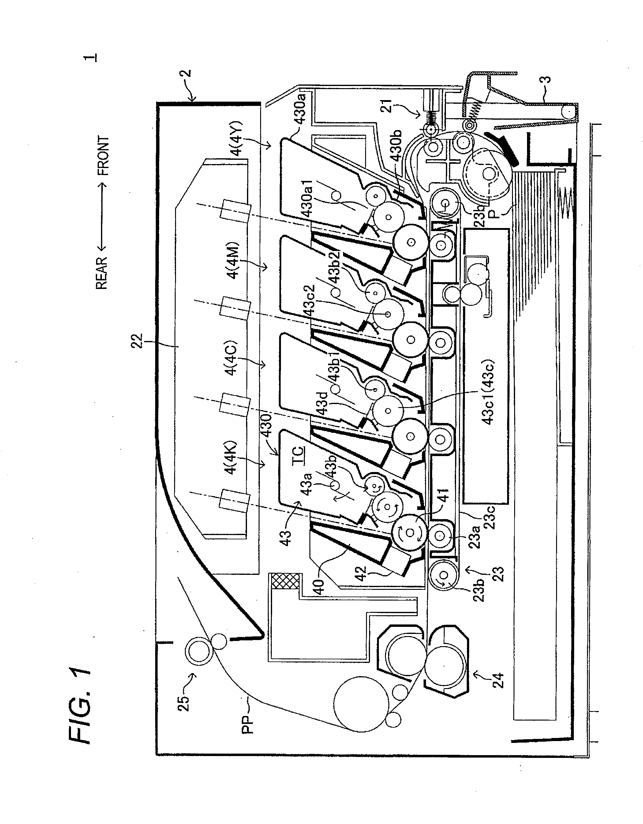
[0034]FIG. 1 is a side sectional view showing the overall configuration of a laser printer 1 which is an example of an image forming apparatus to which one embodiment of the invention is applied. The laser printer 1 is adapted so as to form an image (hereinafter referred to as a toner image) by a non-magnetic monocomponent toner serving as a fine powdery dry developer on a paper P which is a sheet-like recording medium while transporting the paper P along a paper transport path PP (paper path) inside the printer.

[0035]In addition, in the following description, a direction (i.e., a tangential direction at an arbitrary position of the paper transport path PP) in which the paper P is transported along the paper transport path PP in FIG. 1 is referred to as “a paper transport direction”. Additionally, the right side in the drawing is referred to as the “front side”, and the left...


PUM


Abstract

A developing device for an image forming apparatus may include a seal and a casing to prevent leakage of developer. In some examples, the seal member may include multiple side surfaces while the casing may include projections that may abut and contact various surfaces of the seal member. According to one arrangement, the casing may include first, second and third protrusions, where each protrusion is configured to abut and contact a corresponding surface of the seal member. Additionally, the second projection may protrude in a position inside of the first projection while the third projection may protrude in a position between the first and second projections.

Description

CROSS REFERENCE TO RELATED APPLICATION[0001]The present application is a continuation of U.S. patent application Ser. No. 13 / 053,330 filed Mar. 22, 2011, which claims priority from Japanese Patent Application No. 2010-093602, which was filed on Apr. 15, 2010, the disclosure of which is herein incorporated by reference in its entirety.TECHNICAL FIELD[0002]Apparatuses and devices consistent with the present invention relate to a non-magnetic monocomponent developing device and an image forming apparatus including the developing device.BACKGROUND[0003]As this type of device, a device (so-called developing cartridge) disclosed in JP-2009-63635-A is known. This device is adapted so as to be detachably mounted on a body portion in an image forming apparatus, such as a laser printer. This device is adapted so as to supply a charged non-magnetic monocomponent developer to the surface of a photosensitive body provided within the image forming apparatus, and thereby develop an electrostatic l...

Claims


Application Information

Patent Timeline
Patent Type & Authority Applications(United States)
IPC IPC(8): G03G15/08
CPCG03G15/0898G03G15/0817G03G2215/0614
Inventor XU, FANYASUDA, TAKASHIHORINOE, MITSURU
Owner BROTHER KOGYO KK
Why Eureka
Try Eureka