Producing method for fuel cell separator

a technology of fuel cell separator and production method, which is applied in the manufacture of fuel cells, electrochemical generators, and final products. it can solve the problems of deterioration and peeling of the coating layer on the metallic foil, affecting the sealing performance, and reducing the strength of the metallic foil

Active Publication Date: 2019-02-28
TOYOTA JIDOSHA KK
View PDF2 Cites 0 Cited by
  • Summary
  • Abstract
  • Description
  • Claims
  • Application Information

AI Technical Summary

Benefits of technology

[0018]According to the present disclosure, even if the separator base member is press-formed after the surfaces of the core member are co

Problems solved by technology

However, if a crack is generated in the metallic foil in the above manner, the strength of the metallic foil becomes decreased, and the coat layers formed on the metallic foil are likely to be deteriorated and peel off, and thus the sealing performance might be deteriorated.
Unfortunately, in the leakage examination method of the related art described in JP 2016-038981 A, if the crack generated in the metallic foil is covered with the coating material forming the

Method used


Image

  • Producing method for fuel cell separator
  • Producing method for fuel cell separator
  • Producing method for fuel cell separator

Examples


Embodiment Construction

[0024]Hereinafter, a configuration of the present disclosure will be described in detail based on one example of an embodiment shown in the drawings. As one example, the case in which the present disclosure is applied to a fuel cell installed in a fuel cell vehicle or a fuel cell system including this fuel cell will be exemplified, but an application range of the present disclosure is not limited to such an example.

Configuration of Fuel Cell Stack Including Separators

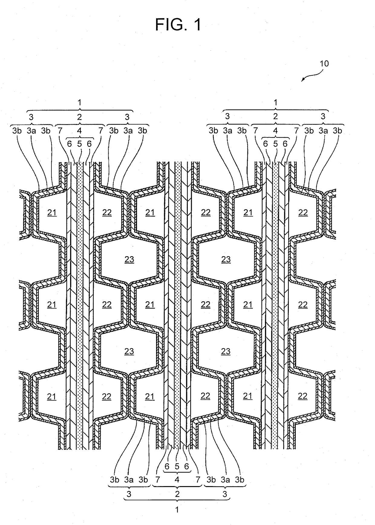
[0025]FIG. 1 is a drawing of a major part of a fuel cell stack (fuel cell) 10 in a sectional view. As shown in FIG. 1, in the fuel cell stack 10, multiple cells (single cells) 1 as base units are stacked. Each cell 1 is a solid polymer fuel cell that generates an electromotive force by electrochemical reaction between an oxidant gas (such as air) and a fuel gas (such as hydrogen). Each cell 1 includes: a MEGA 2; and separators (fuel cell separators) 3 in contact with this MEGA 2 so as to partition this MEGA 2 by the sep...


PUM


Abstract

There are included a preparing step of preparing a separator base member having a core member of which surfaces are coated with a coating material having a higher radioparency than that of the core member; a press-forming step of press-forming the separator base member in a predetermined shape; and an examining step of examining the separator base member after the press-forming step using an X-ray having an output at which the X-ray passes through the coating material.

Description

INCORPORATION BY REFERENCE[0001]The disclosure of Japanese Patent Application No. 2017-166909 filed on Aug. 31, 2017 including the specification, drawings and abstract is incorporated herein by reference in its entirety.BACKGROUND1. Technical Field[0002]The present disclosure relates to a producing method for a fuel cell separator having a core member of which surfaces are formed with coat layers.2. Description of Related Art[0003]A fuel cell (also referred to as a fuel cell stack in some cases) is configured such that a cell (single sell) is formed by holding an electrolyte membrane between an anode and a cathode (also referred to as a cell of a fuel cell in some cases), and multiple cells are laid on one another (stacked) with separators interposed therebetween.[0004]For example, a cell of a solid polymer fuel cell includes a membrane electrode assembly (MEA) composed by an electrolyte membrane having ionic permeability, and an anode catalyst layer (electrode layer) and a cathode ...

Claims


Application Information

Patent Timeline
IPC IPC(8): H01M8/0247H01M8/0228H01M8/0206H01M8/0213
CPCH01M8/0247H01M8/0228H01M8/0206H01M8/0213H01M8/0258H01M8/026Y02E60/50Y02P70/50
Inventor NOBATA, YASUHIRO
Owner TOYOTA JIDOSHA KK
Why Eureka
Try Eureka