Illumination lighting device, discharge lamp lighting device, and vehicle headlamp lighting device using same

a lighting device and discharge lamp technology, applied in the direction of electric variable regulation, process and machine control, instruments, etc., can solve the problem of greater ground fault current than the lamp current obtained, and achieve the effect of reducing the amount of power supplied to the lamp securely

Inactive Publication Date: 2011-08-11
PANASONIC CORP
View PDF16 Cites 24 Cited by
  • Summary
  • Abstract
  • Description
  • Claims
  • Application Information

AI Technical Summary

Benefits of technology

An object of the present invention is to accurately detect a ground fault that occurs when an output terminal of a lighting device has a certain level of impedance, and to perform a protective operation such as stopping the lighting device, in order to prevent damage to the lighting device. Another object of the present invention is to accurately detect a ground fault and perform a protective operation when a ground fault occurs at either side of the output terminal.
According to this configuration, the detection signal of the first current detection means and the detection signal of the second current detection means, which result from the ground-fault current, are of additive polarities. Therefore, even when a ground fault occurs at either side of the output terminal to which the load circuit including the lamp is connected, or even when the ground fault occurs when there is a certain level of impedance, the amount of power supplied to the lamp can be reduced securely. Especially when the lamp is a discharge lamp, secure detection of the ground fault and a protective operation can be performed under the condition that the discharge lamp is turned off due to an insufficient amount of power supplied to the lamp due to the ground fault. The additive polarities mean that the polarities of the detection signals both of the first and second current detection means become positive or negative.

Problems solved by technology

However, the disadvantage is that the ground-fault current becomes greater than the lamp current obtained at the time of lighting, because the sensing resistors become smaller than at the time of the normal lighting.

Method used


Image

  • Illumination lighting device, discharge lamp lighting device, and vehicle headlamp lighting device using same
  • Illumination lighting device, discharge lamp lighting device, and vehicle headlamp lighting device using same
  • Illumination lighting device, discharge lamp lighting device, and vehicle headlamp lighting device using same

Examples


embodiment 1

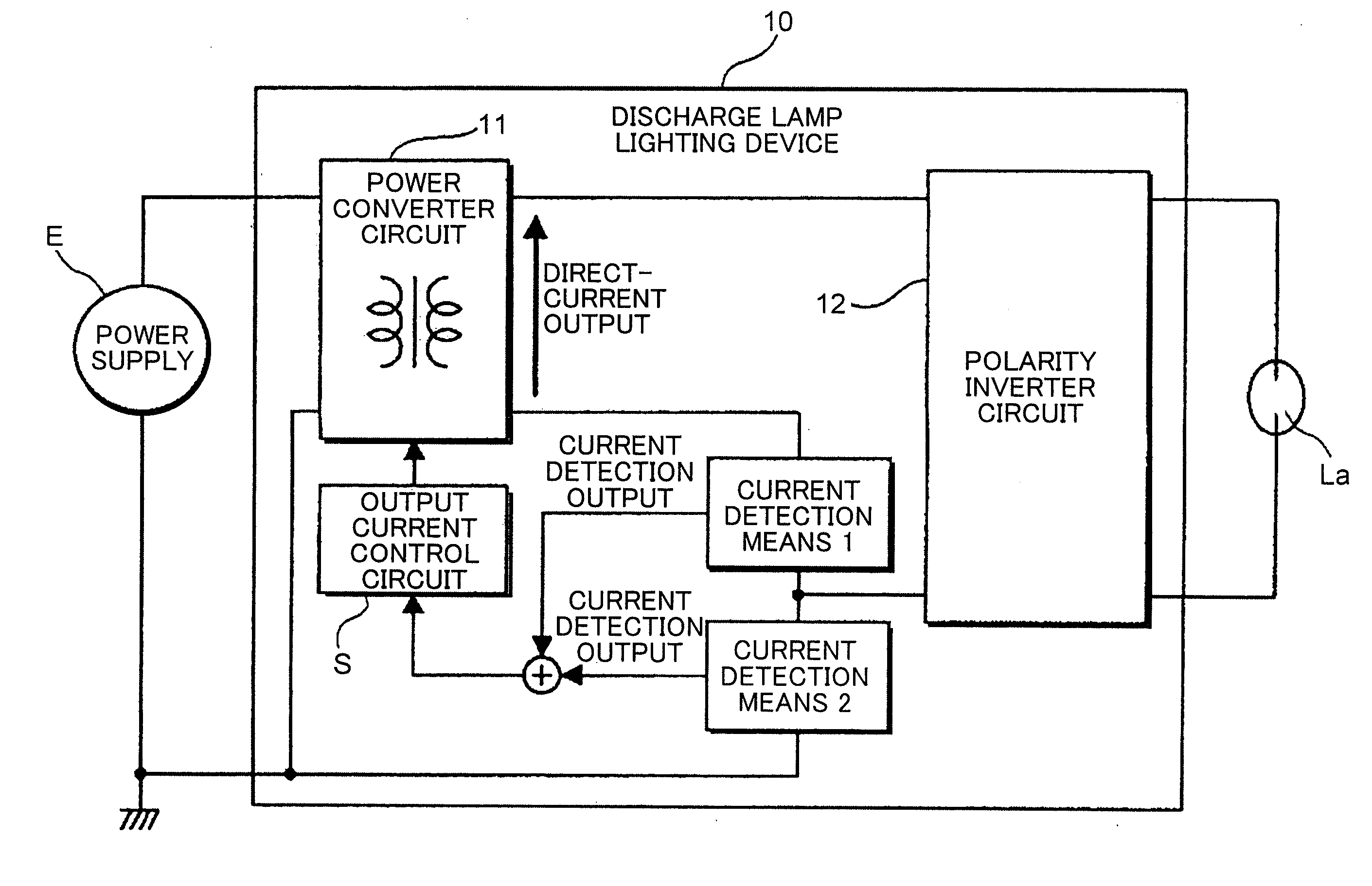
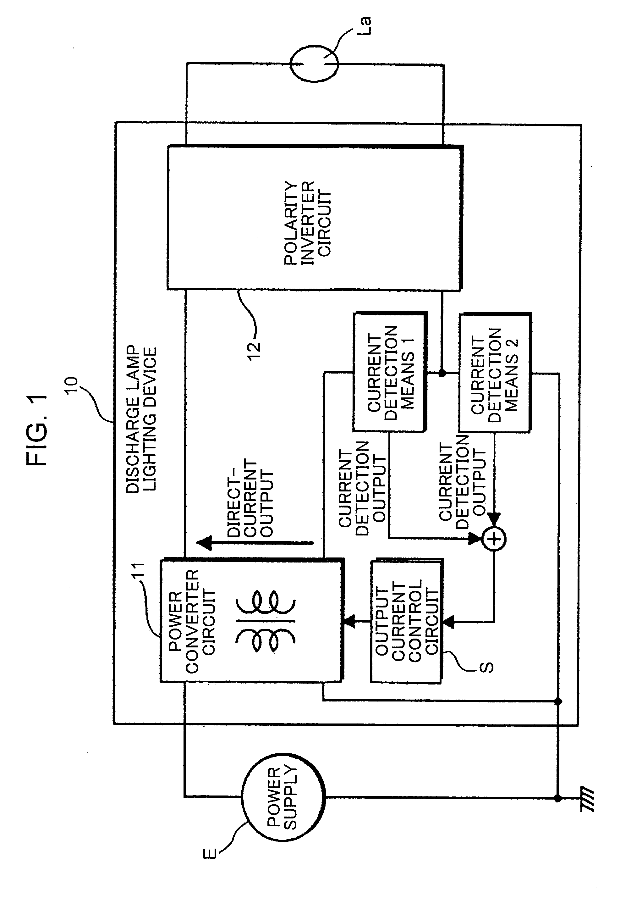
FIG. 1 is a block diagram showing a basic embodiment of the present invention. A power converter circuit 11 configuring a discharge lamp lighting device 10 has a structure in which a galvanic isolation is obtained between the input side terminal to which a power supply E is connected and the output side terminal by means a transformer or the like. The output terminal of the power converter circuit 11 is provided with current detection means 1 and current detection means 2 as output detection means. The output of the power converter circuit 11 is regulated by an output current control circuit S based on current detection outputs of these current detection means 1 and 2. Of the output detection means that are provided at the output terminal of the power converter circuit 11, the current detection means 1 for detecting an output current such as a lamp current is provided at one end of the output terminal of the power converter circuit 11.

In the configuration shown in FIG. 1, in additio...

embodiment 2

FIG. 4 shows a specific embodiment of the present invention. A DC-DC converter circuit 11 converts the power of a direct-current power supply E into a voltage required by the discharge lamp La. The direct-current output of the DC-DC converter circuit 11 is converted into an alternating voltage by the inverter circuit 12. This converted voltage is supplied to the discharge lamp La. The discharge lamp La is supposedly a high-intensity discharge lamp (HID). Thus, a starting circuit 13 is connected between the output of the inverter circuit 12 and the discharge lamp La. The starting circuit 13 is a circuit that applies a high voltage to the discharge lamp La to start the discharge.

In the DC-DC converter circuit 11 serving as the power converter circuit, a power supply E is connected to a primary winding of a transformer 111 via a switching element 112. The DC-DC converter circuit 11 indicates a switching regulator that has a configuration in which a current 11 from the power supply E is...

embodiment 3

A third embodiment is shown in FIG. 6. The main circuit configuration shown in FIG. 6 is the same as that of the embodiment shown in FIG. 4. The difference with the one shown in FIG. 4 is that, compared to the one end of the output terminal of the DC-DC converter circuit 11 that is connected to the current sensing resistor R1, the other end has a negative potential output with a low potential. However, the purposes of the present invention are the same. When the output potential of the DC-DC converter circuit 11 changes, the polarities of the currents flowing through the output current sensing resistors R1 and R2 are inverted from those shown in the embodiment of FIG. 4, and consequently the polarities of the detection signals are also naturally inverted. However, the operations remain the same.

More specifically, a current flows only to the resistor R1 when the discharge lamp is normally lit, and the potential at the point (a) becomes equal to the potential of the circuit ground (GN...


PUM


Abstract

An illumination lighting device is provided with: a power converter circuit having a configuration in which an input terminal to which a power supply can be connected and an output terminal to which a load circuit including at least a lamp can be connected are galvanically insulated, and having a power regulating function required by the lamp; output detection means which is provided at the output terminal of the power converter circuit and has first current detection means and second current detection means; and a control circuit for regulating the output of the power converter circuit based on a result of detection performed by the output detection means, wherein one end of the output of the power converter circuit is connected to one end of the load circuit via the first current detection means, one end of an input of the power converter circuit is connected to the one end of the load circuit via the second current detection means, the output detection means has the result of the detection which is a synthesized signal of detection outputs of the first current detection means and the second current detection means, a current pathway, through which a ground-fault current flows from the one end of the input of the power converter circuit to the one end of the output of the power converter circuit via the first current detection means and the second current detection means, is formed when a ground fault occurs at a load terminal of the load circuit, and a detection signal of the first current detection means and a detection signal of the second current detection means that result from the ground-fault current are of additive polarities.

Description

TECHNICAL FIELDThe present invention relates to an illumination lighting device, a discharge lamp lighting device, and a vehicle headlamp lighting device using the same. Particularly, the present invention relates to protective control performed when a ground fault occurs at output terminals.BACKGROUND ARTPatent Document 1, for example, discloses a power control technology for converting a direct-current power supply, which is obtained by rectifying and smoothing a battery or an alternating current, into a power required by a discharge lamp, in order to stably light the discharge lamp. In this technology, a lamp current command value that is supplied to the discharge lamp is set based on a lamp voltage detection value, and the control variable of a power converter circuit configuring a discharge lamp lighting circuit is regulated based on the calculated difference between the control variable and a lamp current detection value.A technology for suppressing a ground-fault current is s...

Claims


Application Information

Patent Timeline
Patent Type & Authority Applications(United States)
IPC IPC(8): B60Q1/02H05B37/02H05B44/00
CPCH05B41/2882Y02B20/208H05B41/2921Y02B20/00
Inventor NAKAMURA, TOSHIAKI
Owner PANASONIC CORP
Why Eureka
Try Eureka