
Plating method and plating apparatus

a plating apparatus and plating method technology, applied in the direction of sealing devices, fluid tightness measurement, instruments, etc., can solve the problems of increasing affecting the maintenance effect, and reducing so as to reduce the time required for maintenance, the effect of quickly detecting serious troubl

Active Publication Date: 2013-10-03
EBARA CORP
View PDF5 Cites 22 Cited by
  • Summary
  • Abstract
  • Description
  • Claims
  • Application Information

AI Technical Summary

Benefits of technology

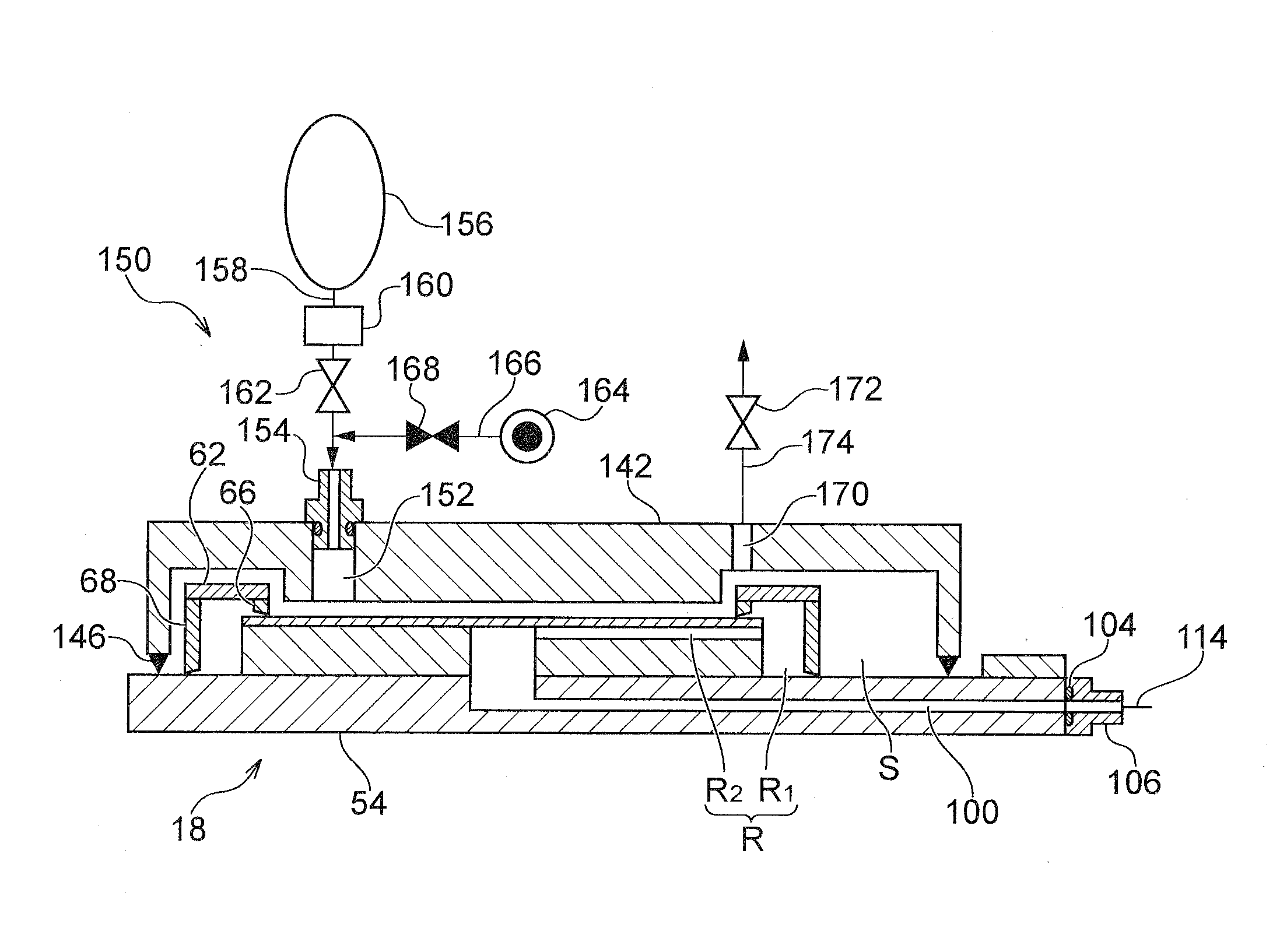
The present invention provides a plating method and a plating apparatus that can quickly and securely detect serious failure of a sealed state of a sealing member and can securely detect leakage of even a trace amount of plating solution prior to plating of a substrate. The method includes a first-stage leakage test and a second-stage leakage test, which can make it early and quickly detect serious trouble with the sealing of the substrate holder, making it possible to take appropriate action on the sealing trouble. The leakage test also makes it possible to infer the cause of leakage and early detect trouble with the sealing member, thereby reducing a time required for maintenance.

Problems solved by technology

However, it is fairly difficult to achieve completely sealed state because of deterioration of the sealing member or other causes.
Use of such a plating solution makes it more difficult to establish the completely sealed state.
It is also generally difficult to detect leakage of the plating solution into the substrate holder.
The plating solution attached to the substrate may be transferred to a substrate transport device and may contaminate the plating apparatus in its entirety.
In addition, the leaked plating solution may corrode electrical contacts, resulting in poor feeding of electric current.
It is generally difficult to determine the sealed state of the sealing member merely by measuring the pressure in the internal space in the substrate holder after evacuating or pressurizing the internal space.
Moreover, when a trace amount of plating solution has leaked, a volume ratio of a volume of the internal space to the amount of the leaked plating solution is considerably high and, inversely, a change in the pressure in the internal space is considerably small.
Therefore, even a high-precision pressure sensor could fail to detect the sealed state.
The leakage of the plating solution in the substrate holder can cause corrosion of the electrical contacts of the substrate holder, an increase in the electrical contact resistance, and the like.

Method used


Image

  • Plating method and plating apparatus
  • Plating method and plating apparatus
  • Plating method and plating apparatus

Examples


Embodiment Construction

[0042]Preferred embodiments of the present invention will now be described in detail with reference to the drawings.

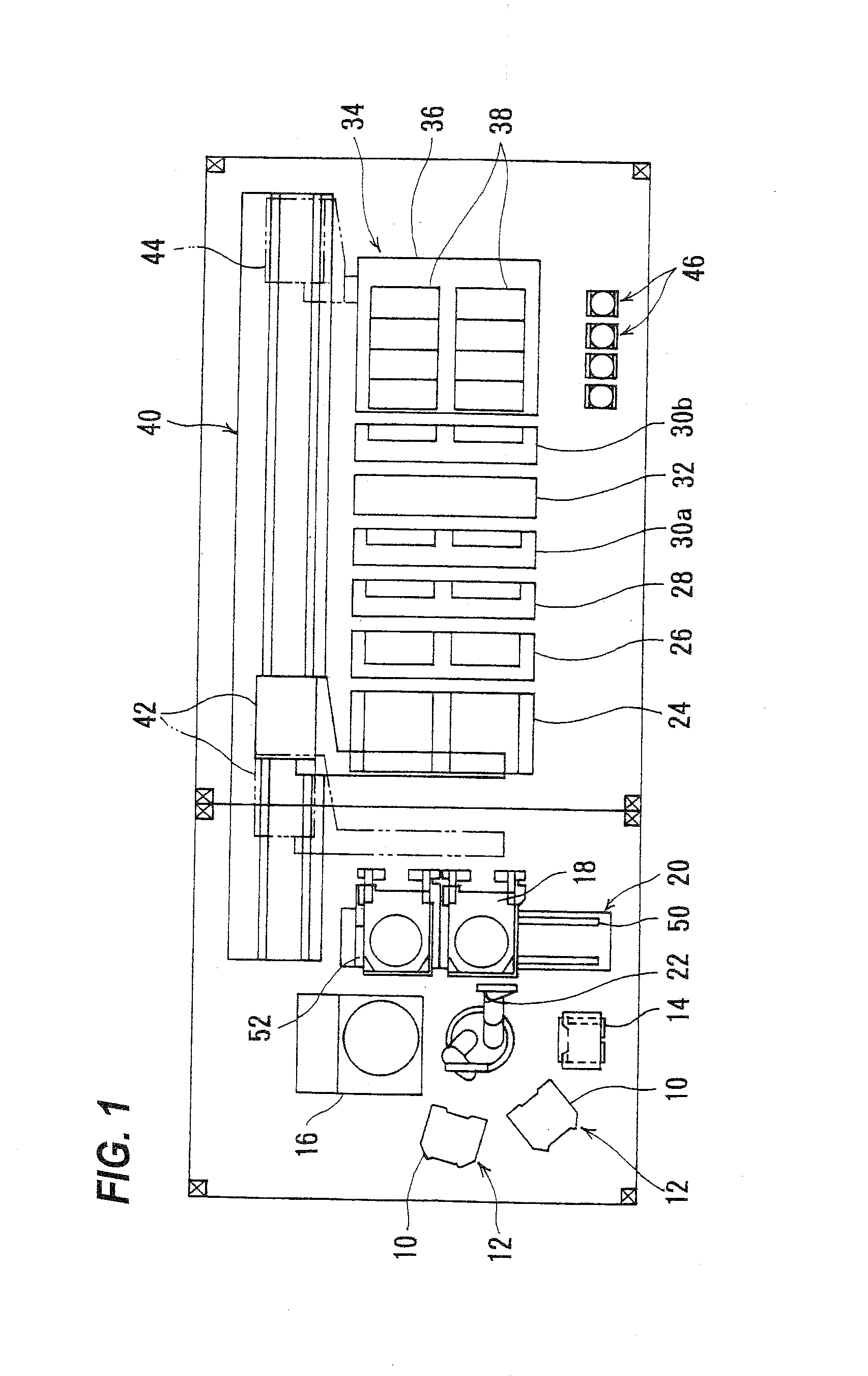
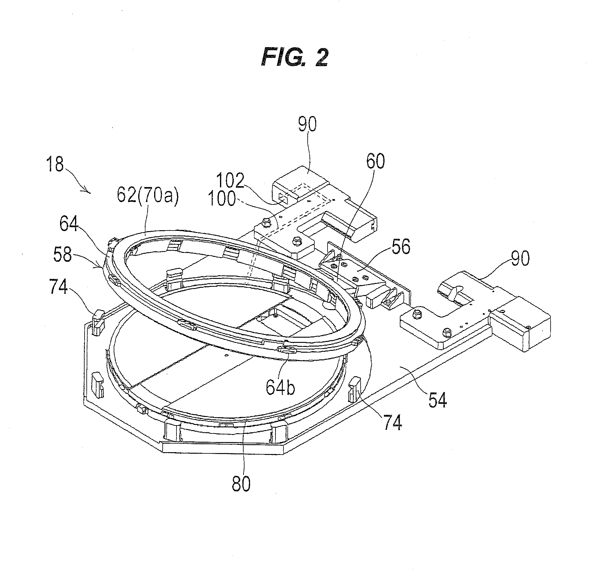
[0043]FIG. 1 shows an overall layout plan view of a plating apparatus according to an embodiment of the present invention. As shown in FIG. 1, the plating apparatus includes two cassette tables 12 each receives thereon a cassette 10 in which substrates W, such as semiconductor wafers, are housed, an aligner 14 for aligning an orientation flat or a notch of the substrate in a predetermined direction, and a spin rinse drier 16 for drying the substrate after plating by rotating it at a high speed. Near these units is provided a substrate loading unit 20 on which the substrate holder 18 is placed. This substrate loading unit 20 is configured to load the substrate into the substrate holder 18 and unload the substrate from the substrate holder 18. Further, in the center of these units is disposed a substrate transport device 22 which is a transport robot for transporting the...


PUM


Abstract

A plating method includes holding a substrate with a substrate holder while bringing a sealing member into pressure contact with a peripheral portion of the substrate to form an enclosed internal space in the substrate holder; performing a first-stage leakage test of the substrate holder by producing a vacuum in the internal space and checking whether pressure in the internal space reaches a predetermined vacuum pressure within a certain period of time; and if the substrate holder has passed the first-stage leakage test, performing a second-stage leakage test of the substrate holder by closing off the internal space after producing the vacuum therein and checking whether a change in the pressure in the internal space reaches a predetermined value within a certain period of time.

Description

CROSS REFERENCE TO RELATED APPLICATION[0001]This document claims priority to Japanese Patent Application No. 2012-071546, filed Mar. 27, 2012, the entire contents of which are hereby incorporated by reference.BACKGROUND OF THE INVENTION[0002]1. Field of the Invention[0003]The present invention relates to a plating method and a plating apparatus for plating a surface of a substrate, and more particularly to a plating method and a plating apparatus for forming a plating film in fine interconnect trenches, holes, or resist openings provided on a surface of a substrate, such as a semiconductor wafer, or for forming bumps (extruding electrodes), to be electrically connected to electrodes of a package, on a surface of a semiconductor wafer. A plating method and a plating apparatus according to the present invention can also be used for filling via holes with metal in manufacturing of an interposer or spacer, having a large number of via plugs penetrating through it, which is to be used in...

Claims


Application Information

Patent Timeline
IPC IPC(8): C25D17/00
CPCC25D17/004C25D21/12C25D17/06C25D17/001C25D7/12C25D7/123G01M3/04G01M3/20G01M3/26G01M3/3263G01M3/3281G01M3/34
Inventor MINAMI, YOSHIOFUJIKATA, JUMPEIKISHI, TAKASHI
Owner EBARA CORP
Learn More