Eureka AIR delivers breakthrough ideas for toughest innovation challenges, trusted by R&D personnel around the world.

Power generator

Inactive Publication Date: 2014-05-08
MITSUMI ELECTRIC CO LTD
View PDF17 Cites 8 Cited by
  • Summary
  • Abstract
  • Description
  • Claims
  • Application Information

AI Technical Summary

Benefits of technology

The power generator in this patent is easy to adjust the frequency of, which means it's dependable and easy to use. This means it can be adjusted quickly and with simple manipulation.

Problems solved by technology

However, it is difficult to readjust the resonant frequency of the power generator after the power generator has been assembled because cumbersome and complicated processes (for example, disassembly process) are required to readjust the resonant frequency of the power generator.

Method used


Image

  • Power generator
  • Power generator
  • Power generator

Examples


first embodiment

[0041]Description will be first given to a power generator 100 according to the first embodiment of the present invention.

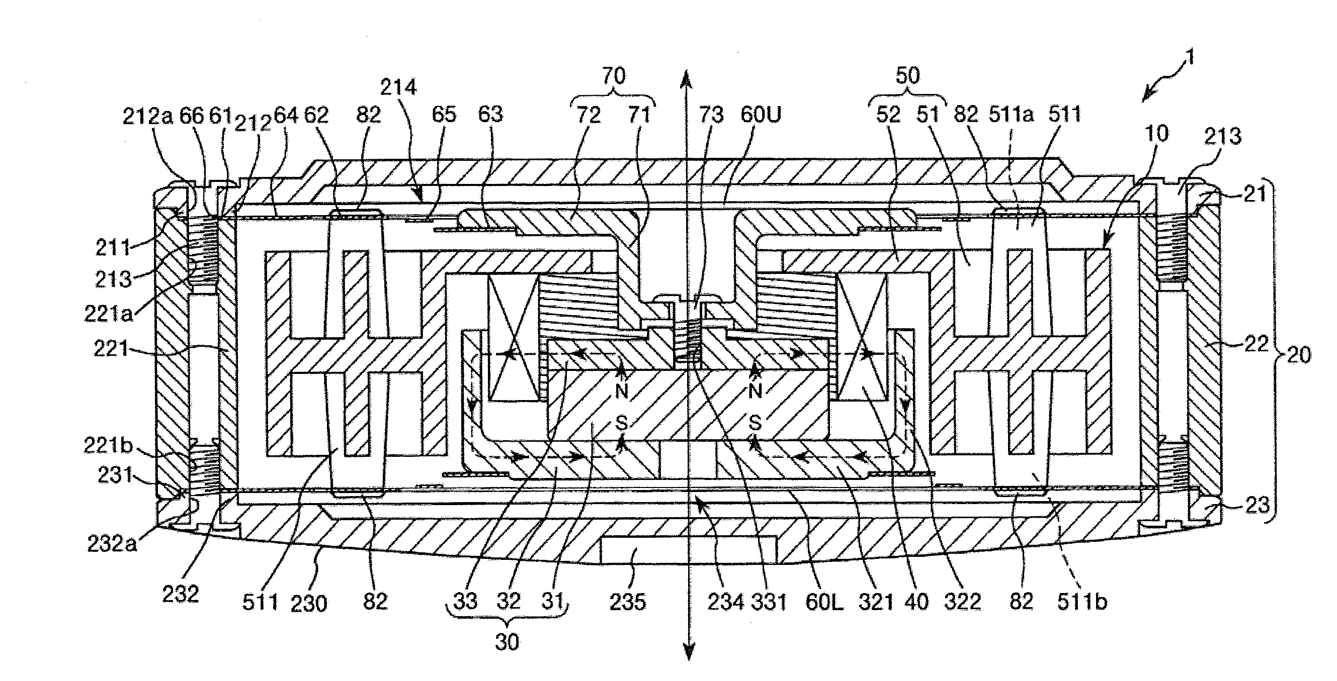
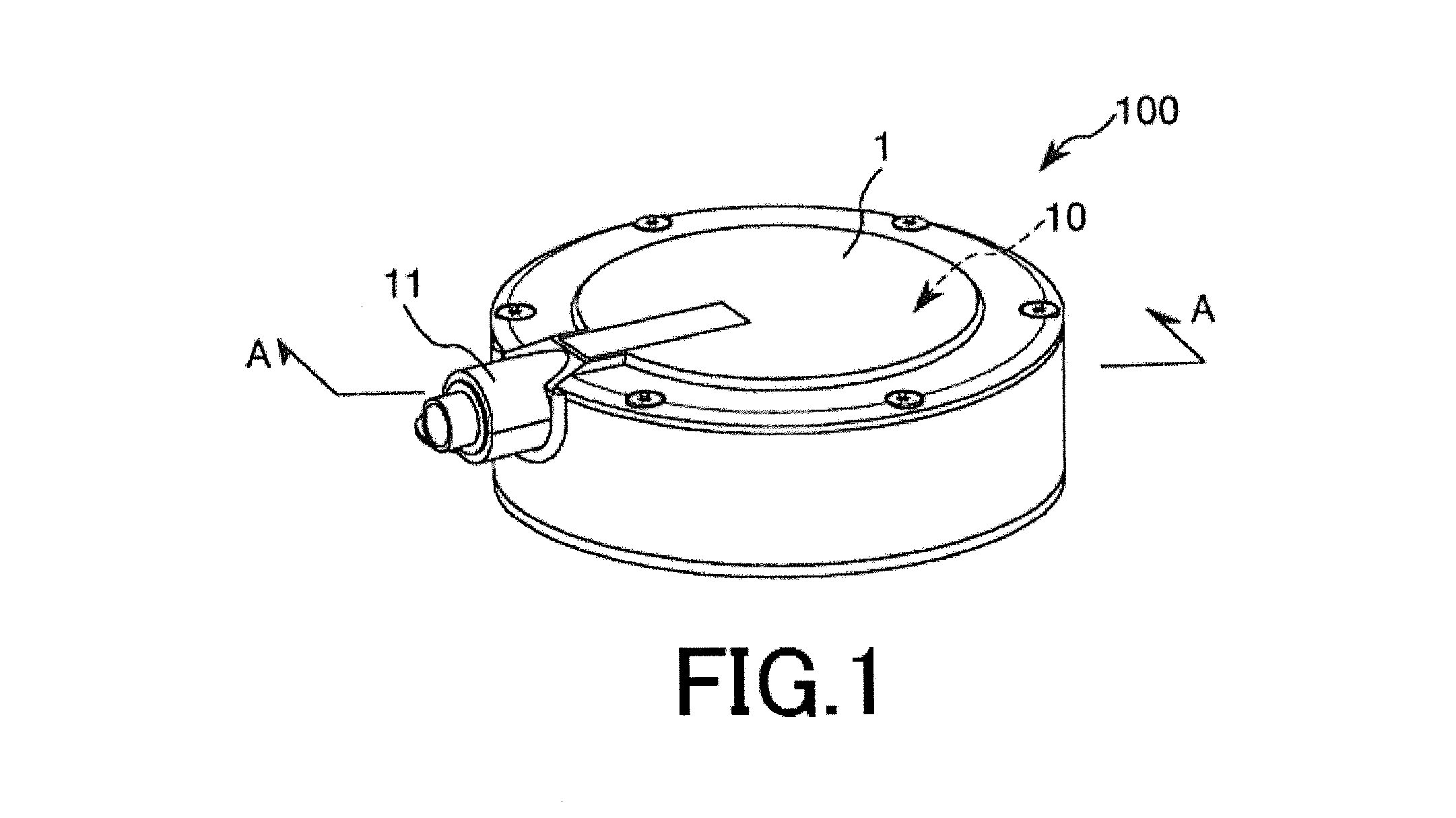
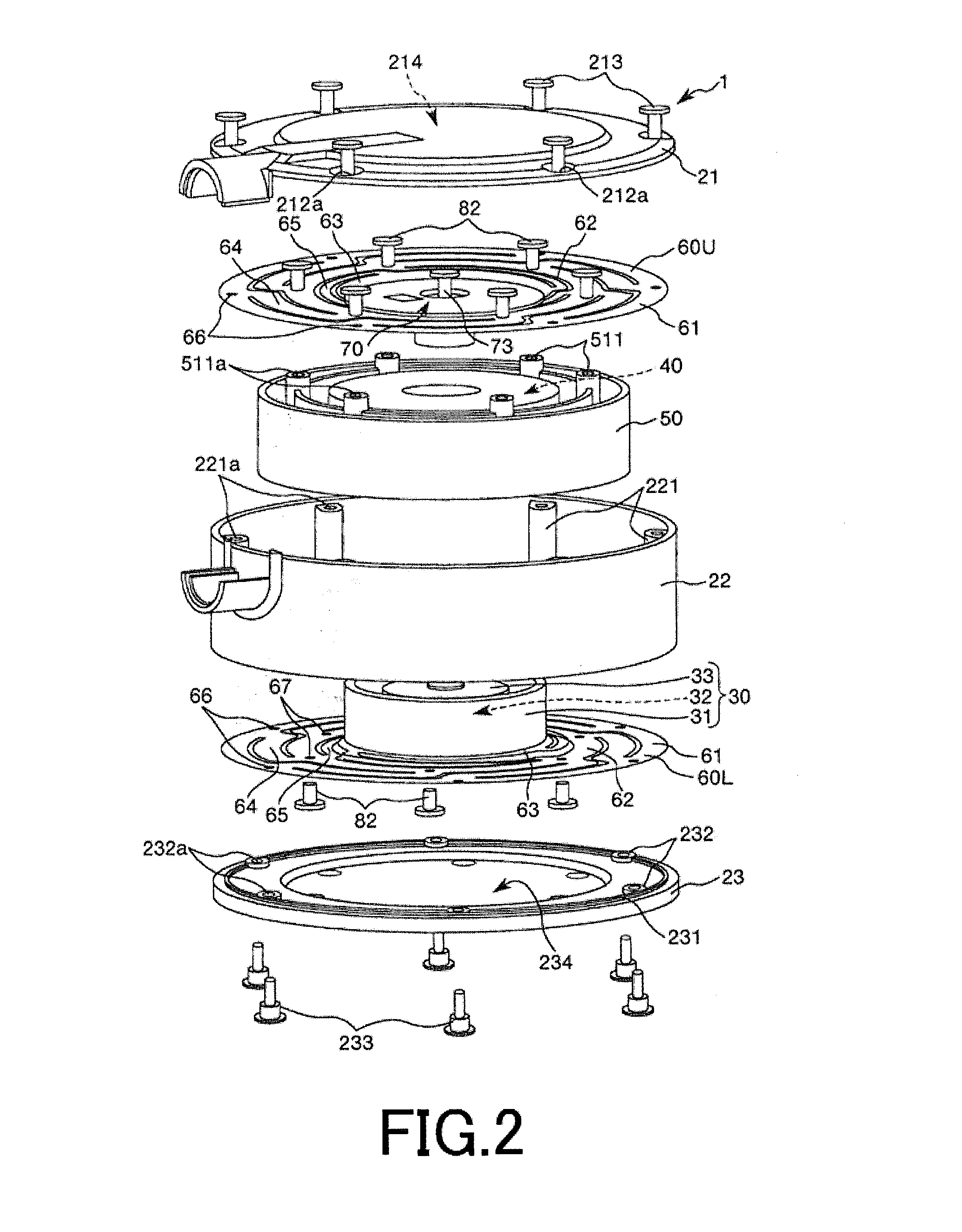
[0042]FIG. 1 is a perspective view showing the power generator 100 according to the first embodiment of the present invention. FIG. 2 is an exploded perspective view showing the power generator 100 shown in FIG. 1. FIG. 3 is a cross-sectional view taken along an A-A line in FIG. 1 (a longitudinal cross-sectional view showing a main unit shown in FIG. 2). FIG. 4 is a planar view showing a leaf spring of the main unit shown in FIG. 2. FIG. 5 is a graph for explaining an effect due to change of a resonant frequency. Each of FIGS. 6 to 8 is a perspective view showing a structure of a first spring constant adjuster. FIG. 9 is a stress distribution map showing a stress distribution of a first spring portion of the leaf spring shown in FIG. 4 (FIG. 9a is an overall view and FIG. 9b is an enlarged view showing the vicinity of one end portion of the first spring portion)....

second embodiment

[0133]Next, description will be given to a power generator 100 according to the second embodiment.

[0134]Each of FIGS. 14 to 16 is a perspective view showing a first spring constant adjuster 12 according to the second embodiment of the present invention. FIG. 17 is a planar view for explaining an action of the first spring constant adjuster 12 according to the second embodiment of the present invention. Hereinafter, an upper side in FIG. 14 is referred to as “upper” or “upper side” and a lower side in FIG. 14 is referred to as “lower” or “lower side”. Further, an upper side in FIG. 15 is referred to as “lower” or “lower side” and a lower side in FIG. 15 is referred to as “upper” or “upper side”. Furthermore, a front side of the paper in each of FIGS. 16 and 17 is referred to as “upper” or “upper side” and a rear side of the paper in each of FIGS. 16 and 17 is referred to as “lower” or “lower side”.

[0135]Hereinafter, the power generator 100 according to the second embodiment will be d...

third embodiment

[0142]Next, description will be given to a power generator 100 according to the third embodiment.

[0143]FIG. 18 is a perspective view showing a structure of the second spring constant adjuster 13. FIG. 19 is a longitudinal cross-sectional view showing a structure of the second spring constant adjuster 13. FIG. 20 is a longitudinal cross-sectional view for explaining an action of the second spring constant adjuster 13. FIG. 21 is a graph for explaining change of the spring constants of the second spring portions 65. Hereinafter, an upper side in each of FIGS. 18 to 20 is referred to as “upper” or “upper side” and a lower side in each of FIGS. 18 to 20 is referred to as “lower” or “lower side”.

[0144]Hereinafter, the power generator 100 according to the third embodiment will be described by placing emphasis on the points differing from the power generators 100 according to the first and the second embodiments, with the same matters omitted from description. The power generator 100 accor...


PUM


Abstract

A power generator 100 of the present invention includes a housing 20; a permanent magnet 31 disposed in the housing 20 so that the permanent magnet 31 can be displaced in a magnetization direction thereof; a coil 40 disposed in the housing 20 so as to surround the permanent magnet 31 without contacting with the magnet 39; a coil holding portion 50 disposed between the housing 20 and the permanent magnet 31; a pair of leaf springs 60U, 60L disposed in the housing 20 so as to be opposed to each other through at least the permanent magnet 31, the coil 40 and the coil holding portion 50; and at least one of a first spring constant adjuster 12 for adjusting spring constants of the first spring portions 64 and a second spring constant adjuster 13 for adjusting spring constants of the second spring portions 65.

Description

BACKGROUND OF THE INVENTION[0001]1. Field of the Invention[0002]The present invention relates to a power generator.[0003]2. Description of the Prior Art[0004]Recently, various power generators generating electric power by converting vibration energy into electric energy are developed. For example, see a patent document 1 (JP 2011-160548A). A power generator disclosed in the patent document 1 has a main unit for generating electric power and a pair of coil springs provided on the same axis with each other. The power generator is configured to vibrate the main unit by using the pair of coil springs. In the power generator, it is possible to displace a magnet provided in the main unit relative to a coil by utilizing the vibration. As a result, electric voltage is induced in the coil due to electromagnetic induction.[0005]In such power generator, it is possible to adjust a resonant frequency of the power generator (main unit) by some ways such as adding a weight to the main unit and cha...

Claims


Application Information

Patent Timeline
IPC IPC(8): H02K35/02
CPCH02K35/02H02K35/00H02K2213/09
Inventor FURUKAWA, KENICHIYAMADA, KENSUKE
Owner MITSUMI ELECTRIC CO LTD
Why Eureka
Eureka Blog
Learn More