
Ballistic Vest with Duty Belt Suspension System

a suspension system and ballistic vest technology, applied in the field of body armor, can solve the problems of cumbersome hips, high energy consumption, and heavy equipment array, and achieve the effects of easy assemblage, low manufacturing cost, and durable construction

Inactive Publication Date: 2014-05-15
ELBECO
View PDF11 Cites 6 Cited by
  • Summary
  • Abstract
  • Description
  • Claims
  • Application Information

AI Technical Summary

Benefits of technology

This patent describes an integrated ballistic vest that has a durable and effective duty belt suspension system. The front and rear straps allow for shifting of the duty belt relative to the ballistic vest. The clips allow for easy mounting of the duty belt onto the ballistic vest and allow for vertical movement of the duty belt. The weight of the duty belt is carried on the shoulders of the officer wearing the ballistic vest. This integrated design is affordable, easy to assemble, and has simple and effective use.

Problems solved by technology

This array of equipment can present a heavy load for the officer to carry in addition to the substantial weight of the bulletproof vest.
Thus, the duty rig, including the duty belt and the equipment mounted thereon, presents a cumbersome weight on the officer's hips that requires an expenditure of a lot of energy by the officer.
As a result, sitting in a vehicle and other related movements of the officer are limited as the duty rig is not capable of freely moving relative to the ballistic vest.
Anchoring the ballistic vest is an expressed concern in the known prior art, as is represented by the aforementioned patents; however, none of these prior art patents teach a suspension system in which the duty belt is supported from straps integrally formed within the ballistic vest to permit the shifting of the duty belt relative to the ballistic vest for the comfort of the officer wearing the ballistic vest and the duty belt.

Method used


Image

  • Ballistic Vest with Duty Belt Suspension System
  • Ballistic Vest with Duty Belt Suspension System
  • Ballistic Vest with Duty Belt Suspension System

Examples


Embodiment Construction

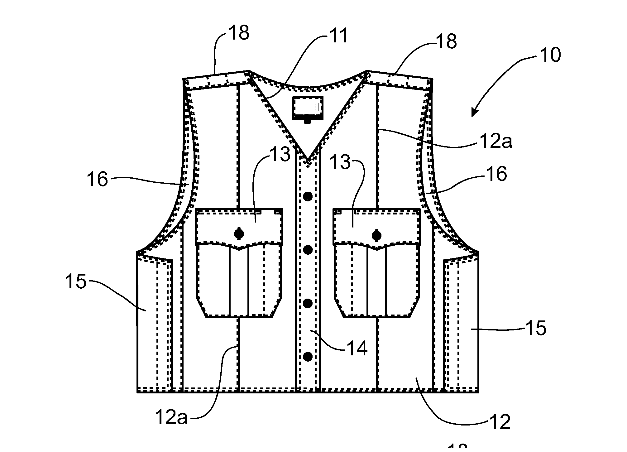
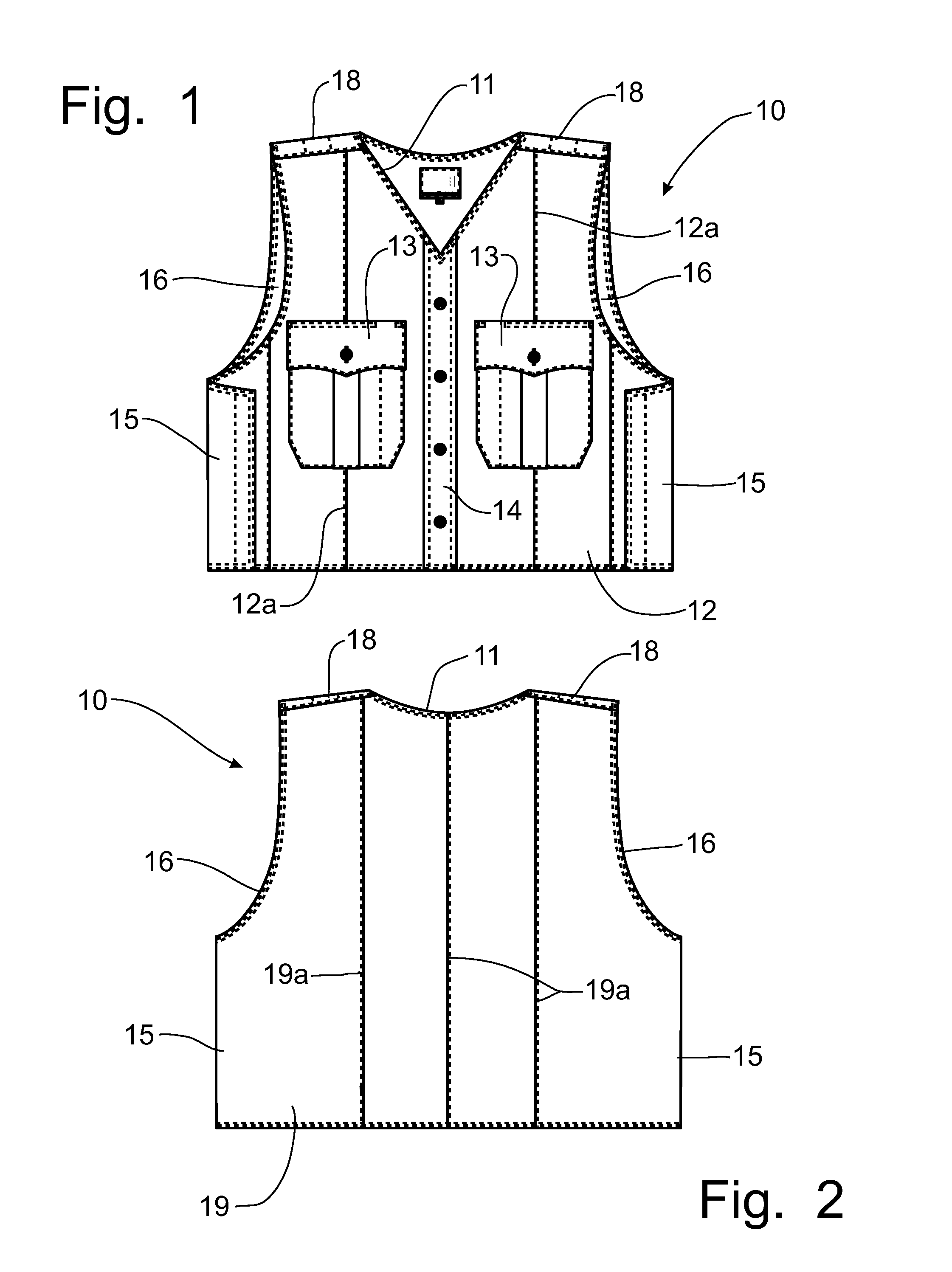
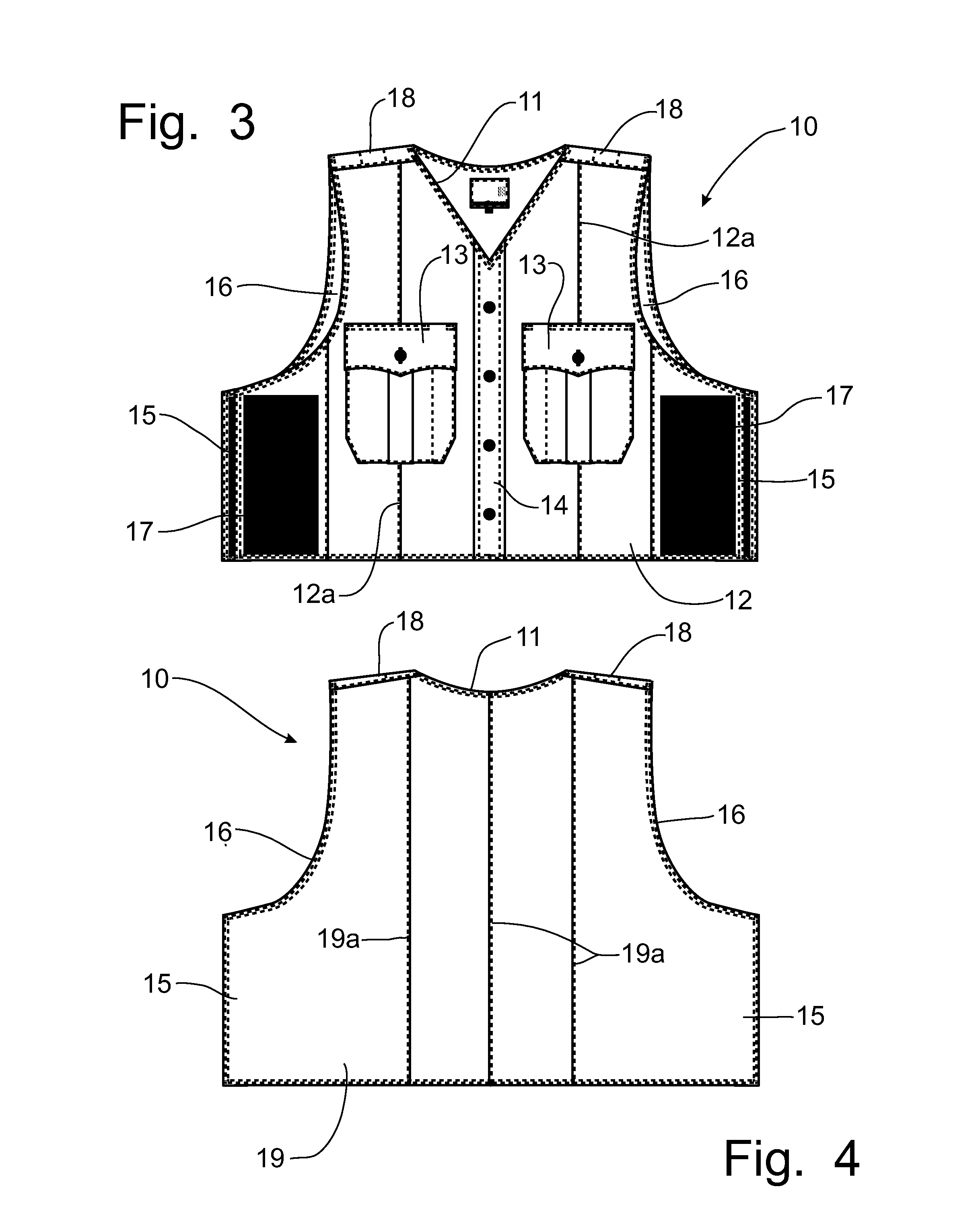
[0060]Referring to FIGS. 1-6A, a bulletproof vest, sometime referred to as body armor, flak vest or a ballistic vest, incorporating the principles of the instant invention can best be seen. The ballistic vest 10 is designed with an opening 11 in the center to allow the vest 10 to be slipped over the head of the person wearing the vest 10 such that there is a front panel 12 lying over the chest of the wearer, as depicted in FIG. 1, and a back panel 19 overlying the back of the wearer, as depicted in FIG. 2. The exterior side of the front panel 12 is configured as an officer's uniform shirt with a pair of functional buttoned shirt pockets 13 and a non-functional buttoned front 14 to simulate a conventional buttoned uniform shirt, even though the ballistic vest 10 is worn by slipping the vest 10 over the wearer's head.

[0061]The sides 15 below the sleeve holes 16 are formed with hook and loop fastener material 17 that can be fastened beneath the wearer's arms once the vest 10 is slipped...


PUM


Abstract

A ballistic vest is formed with an integrated suspension system for supporting the duty belt directly from the ballistic vest. Front and rear support straps can be tunneled into the structure of the ballistic vest and terminate in clip members formed with an interior slot or cavity into which the duty belt can be positioned. The duty belt is loosely contained within the clip members to permit shifting relative to the ballistic vest to the comfort of the officer wearing the apparatus. The clip member can be formed with a latching clevis to engage the strap for positional adjustment of the clip member or with a plurality of horizontal slots for the threading of the strap. The ballistic vest can be manufactured with the appearance of a uniform shirt so that the ballistic vest can be worn as an external garment as part of the officer's uniform.

Description

CROSS-REFERENCE TO RELATED APPLICATIONS[0001]This application claims domestic priority on U.S. Provisional Patent Application Ser. No. 61 / 510,287, filed on Jul. 21, 2011, the content of which is incorporated herein by reference.FIELD OF THE INVENTION[0002]The present invention generally relates to body armor as worn by police officers and, more particularly, to a ballistic vest incorporating a duty belt suspension system to support the duty belt from the ballistic vest.BACKGROUND OF THE INVENTION[0003]A bulletproof vest is typically formed with a front ballistic panel and a rear ballistic panel, which are secured to one another by detachable straps that pass under the arms of the user along the rib cage, and by a pair of shoulder straps that connect upper portions of the front and rear panels and pass over the shoulders of the user. Ballistic vests are conventionally concealed beneath the officer's uniform or worn over top of the officer's uniform, but present a separate article of ...

Claims


Application Information

Patent Timeline
IPC IPC(8): A41F19/00F41H1/02
CPCF41H1/02A41F3/02A41F5/00
Inventor LURIO, DAVID L.BURGOON, STEPHEN T.
Owner ELBECO
Learn More