Decorative cover plate apparatus

Inactive Publication Date: 2014-05-15
KRAMER DUANE F
View PDF1 Cites 3 Cited by
  • Summary
  • Abstract
  • Description
  • Claims
  • Application Information

AI Technical Summary

Benefits of technology

[0013]The present invention is a decorative cover plate apparatus comprising: a mounting bracket having a right side and a left side, comprising a vertical post and a horizontal arm extending from the right side and a horizontal arm extending from the left side, each horizontal arm having a center, and each horizontal arm having an aperture in roughly the center of the horizontal arm, the vertical post having a middle, a top, and a vertical centerline, each of the horizontal arms having a horizontal centerline, wherein the horizontal centerline of the horizontal

Problems solved by technology

Although these and other similar commercially available products are available with simple ornamental designs, none of them is capable of hiding the exposed bolt heads of

Method used


Image

  • Decorative cover plate apparatus
  • Decorative cover plate apparatus
  • Decorative cover plate apparatus

Examples


Example

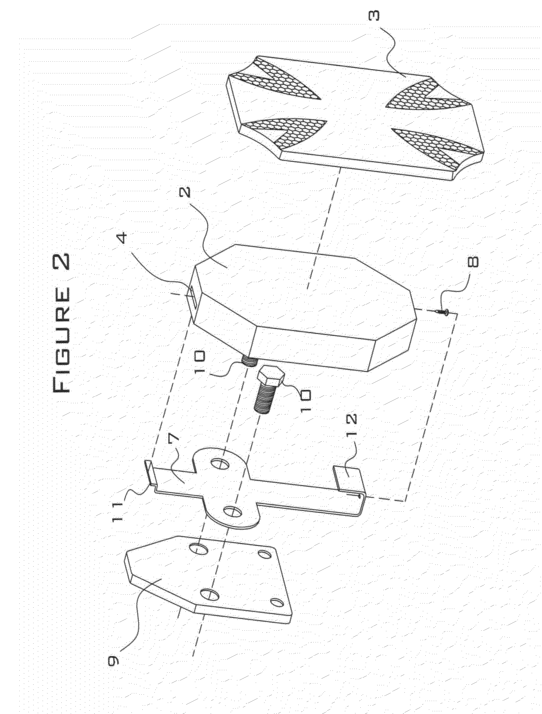
[0061]In the first embodiment, the top tab is formed by a first 90-degree bend (in the direction toward the back side of the cover box) that produces a horizontal portion approximately ⅜-inch long, and a second 90-degree bend that forms an upward-pointing tip having a length of approximately ⅛-inch. In the first embodiment, the bottom tab is formed by a first 90-degree bend (in the direction toward the back side of the cover box) that produces a horizontal portion approximately ½-inch long, and a second 90-degree bead that forms an upward-pointing tip having a length of approximately ½-inch.

Example

[0062]In the second embodiment, the top tab is formed by a first 90-degree bend (in the direction toward the back side of the cover box) that produces a horizontal portion approximately ¼-inch long, and a second 90-degree bend that forms a downward-pointing tip having a length of approximately ¼-inch. In the second embodiment, the bottom tab is formed by a single 90-degree bend (in the direction toward the back side of the cover box) that produces a horizontal portion approximately ½-inch long. Both embodiments of the mounting brackets comprise a hole having a diameter of approximately 3 / 16-inch that is installed in the horizontal portion of the bottom tab.

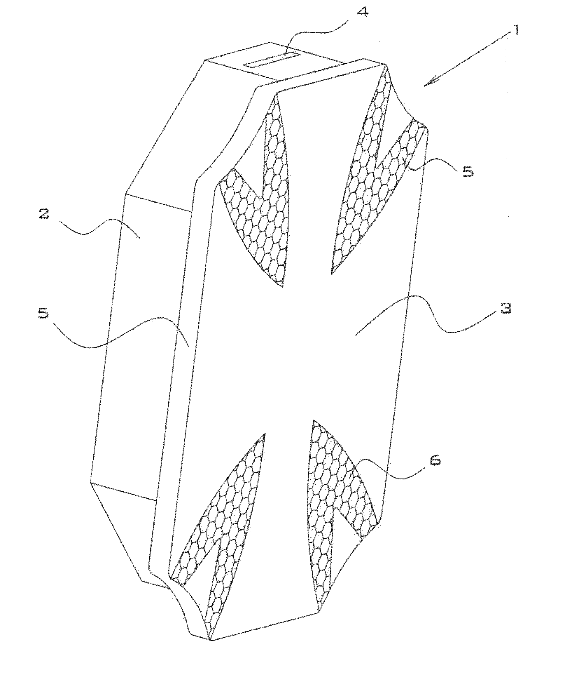
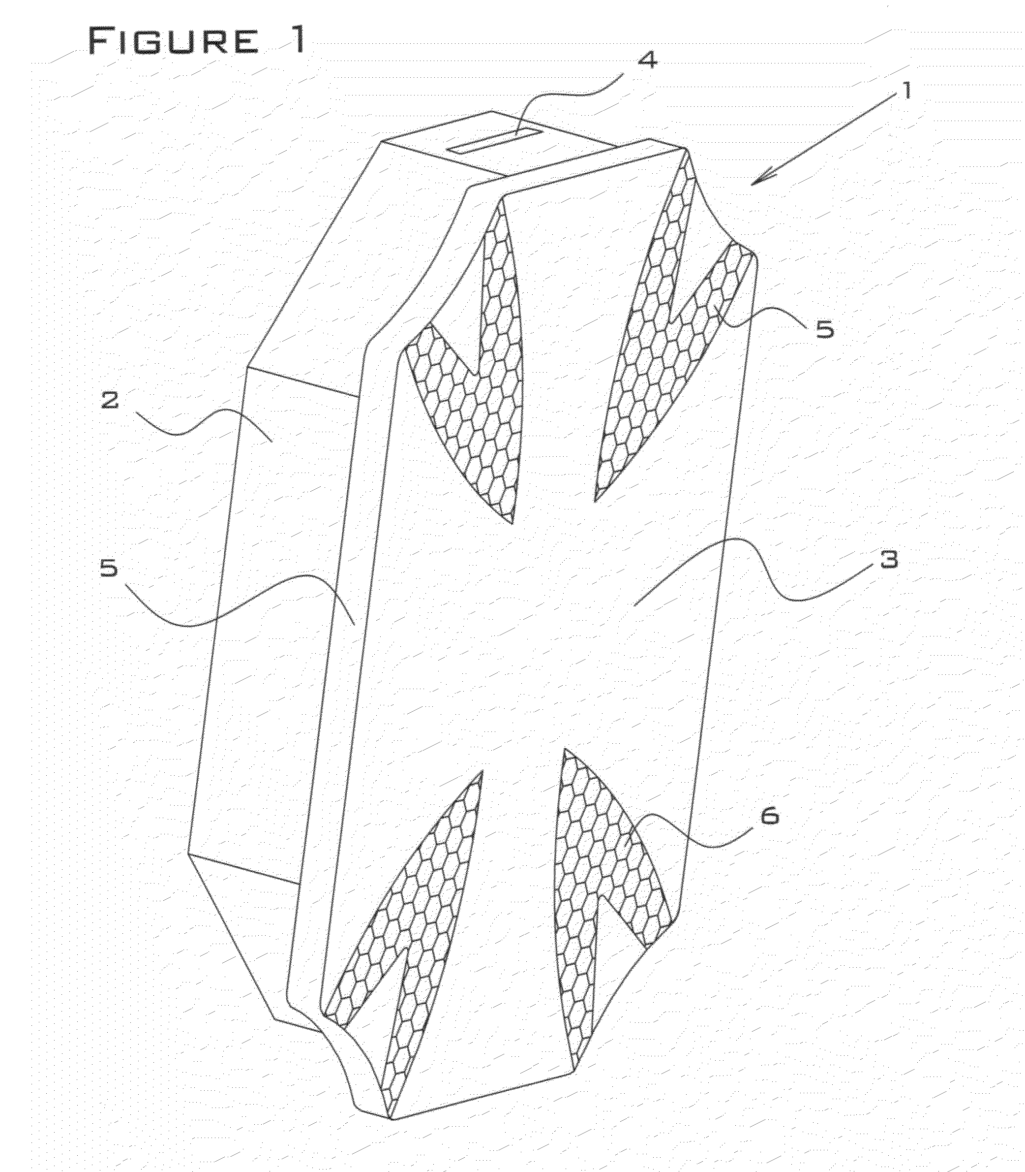
[0063]The cover box of the present invention is preferably hexagonal in shape, which eliminates protruding corners that would otherwise come into contact with adjacent engine parts (for example, the cylinder head). The cover box is manufactured to have sufficient depth (for example, ¾ inch) so that the decorative plate will clear ...


PUM


Abstract

A decorative cover plate apparatus comprising a mounting bracket, a cover box, and a decorative plate. The mounting bracket has a vertical post, two horizontal arms, each with as aperture in roughly the center of the horizontal arm, and top and bottom tabs. The horizontal centerline of the horizontal arms intersects the vertical centerline of the vertical post perpendicularly at a point on the vertical post centerline that is between the middle and the top of the vertical post. The cover box has a top attachment slot and an open back. The decorative plate has an overhanging lip and it at least as wide and as high as the cover box. The top tab of the mounting bracket fits into the top attachment slot on the cover box.

Description

BACKGROUND OF THE INVENTION[0001]1. Field of the Invention[0002]The present invention relates to the field of decorative covers, and more particularly, to an apparatus that serves as a decorative cover over an unused port such as a fuel pump port on an automobile engine.[0003]2. Description of the Related Art[0004]There are several examples of decorative cover designs and one example of temporary engine component covers that are the subject of issued patents or published applications, but none of these inventions includes the novel features of the present invention, most notably:[0005]a mounting bracket that attaches to the engine block using the existing cover plate bolts;[0006]a cover box that effectively covers unsightly bolt heads and flat sealing plates, thereby hiding them from view;[0007]a specialized outer shape of the cover box and decorative plate that allows for an oversized decorative portion of the apparatus that does not contact portions of the engine;[0008]a mounting ...

Claims


Application Information

Patent Timeline
IPC IPC(8): F02B77/00
CPCF02B77/00F02B77/005
Inventor KRAMER, DUANE F.
Owner KRAMER DUANE F
Why Eureka
Try Eureka