Spinous Process Spacer Hammock

a technology of spacers and hammocks, which is applied in the field of spinous process spacer hammocks, can solve the problems of wear away of the spinous process bone, difficult implantation of devices, and inability to stay in place, so as to reduce the distraction, increase the distraction, and reduce the tension

Inactive Publication Date: 2009-01-01
DEPUY SYNTHES PROD INC
View PDF12 Cites 154 Cited by
  • Summary
  • Abstract
  • Description
  • Claims
  • Application Information

AI Technical Summary

Benefits of technology

[0007]In a first embodiment of the present invention, there is provided an interspinous spacer that comprises a flexible strap or ligament that is threaded through two slotted plates positioned on either side of the spinous processes and a means for tensioning the strap and holding it in place once the desired distraction has been achieved. Distraction of the spinous processes is achieved by locating the slots on the straps such that the distance between the slots on each plate is larger than the distance between the spinous processes. Adjustable distraction of the spinous processes may also be achieved by varying the level of tension in the strap. Increasing the level of tension in the strap increases the distraction of the spinous processes (up to the distance between the upper and lower throughholes), while decreasing the level of tension decreases the distraction. In addition, as the ligament is tensioned, the two braces automatically become snugly opposedly positioned against the sides of the spinous processes, thereby helping to keep the device from migrating during use.
[0008]In another embodiment, the spacer comprises two straps or ligaments, one located at the cranial and one at the caudal portions of the device, with each strap being fixed to the respective inner surfaces of two plates positioned on opposing sides of the spinous processes. For this embodiment, there is preferably a centrally located distance adjustment element that connects the two plates and may be adjustable in a medial-lateral direction such that the adjustment changes the tension of the straps and thereby enables distraction of the spinous processes. In one preferred embodiment, the central distance adjustment element is a threaded rod and the plates have threaded holes for mating with the threaded rod. Preferably, the opposed holes are threaded in the opposite direction (right hand versus left hand threads) such that upon turning the threaded rod, the plates will move either away from each other or towards each other, thus either tightening or loosening the strap.

Problems solved by technology

However, many of these devices are either difficult to implant, do not stay in place, or wear away the bone of the spinous process due to poor conformance of the device.

Method used


Image

  • Spinous Process Spacer Hammock
  • Spinous Process Spacer Hammock
  • Spinous Process Spacer Hammock

Examples


Embodiment Construction

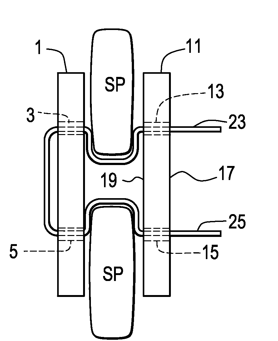
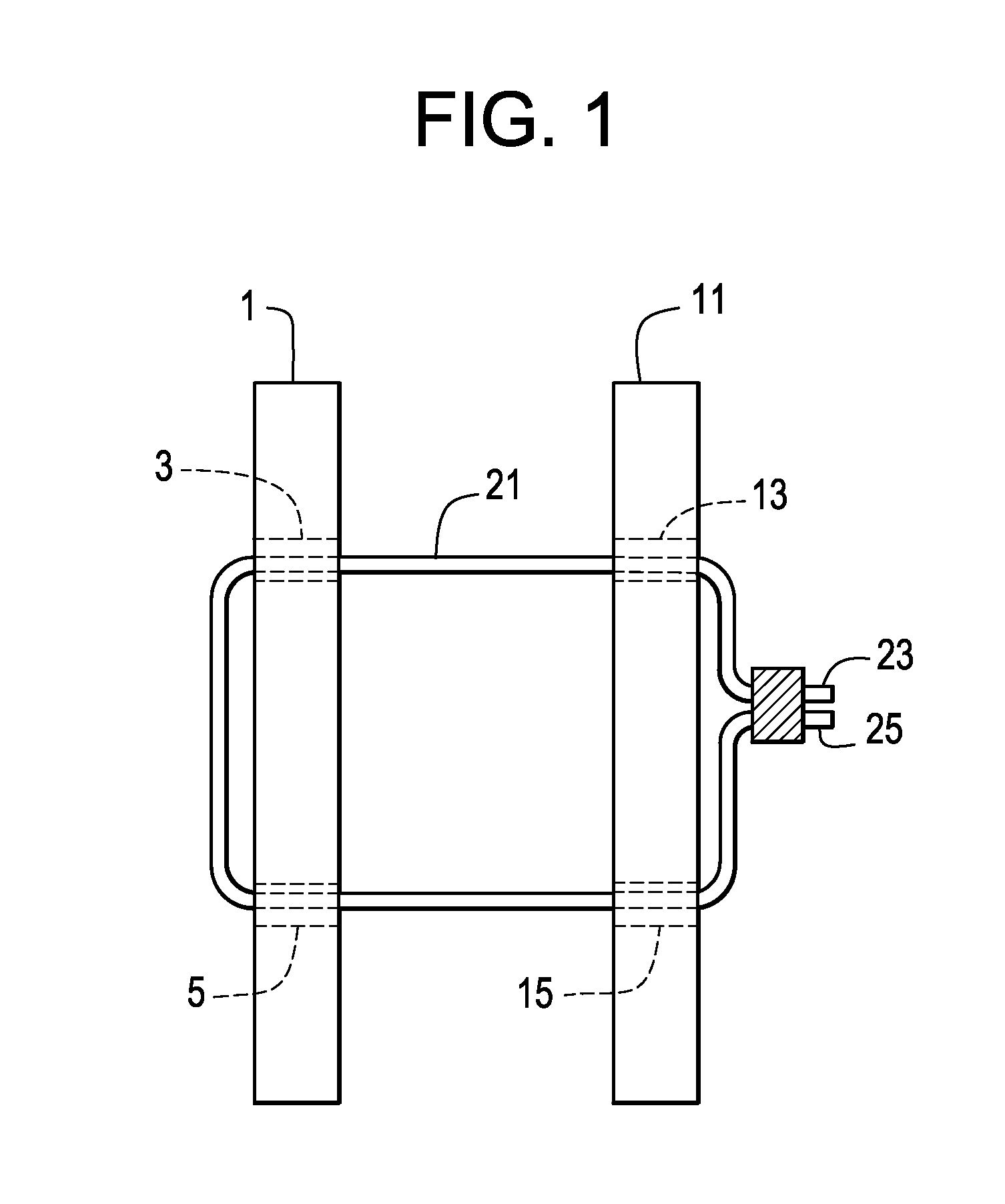
[0017]Now referring to FIG. 1, there is provided an interspinous spacer comprising:[0018]a) a first brace 1 having an upper throughhole 3 and a lower throughhole 5,[0019]b) a second brace 11 having an upper throughhole 13 and a lower throughhole 15,[0020]c) a ligament 21 having a first end 23 and a second end 25,

wherein the ligament extends from the upper throughhole of the first brace through the upper throughhole of the second brace, then through the lower throughhole of the second brace, then through the lower throughhole of the first brace, and

wherein the first end of the ligament is in mechanical connection with the second end of the ligament between the upper throughhole and a lower throughhole of the first brace.

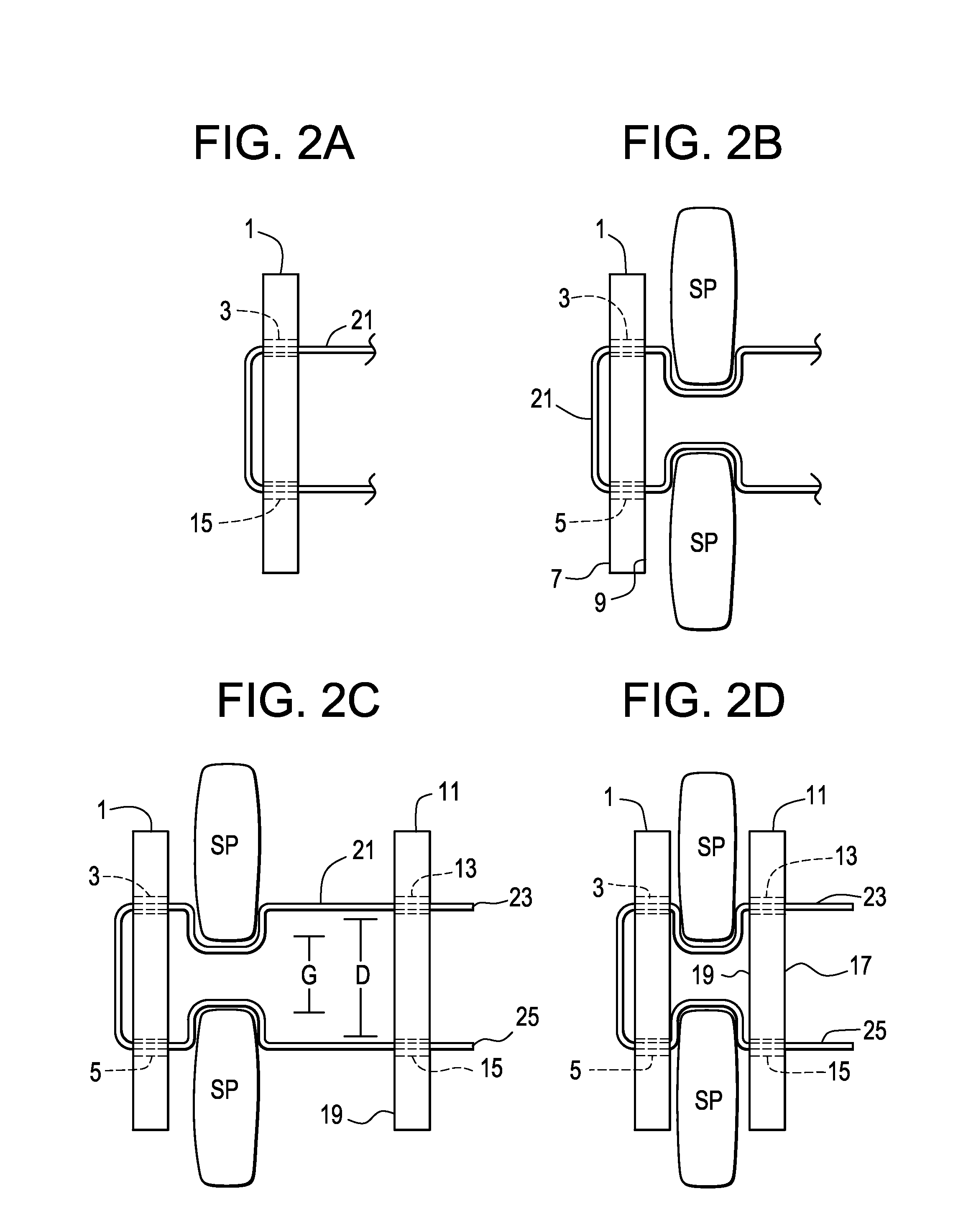
[0021]Now referring to FIGS. 2a-2f, the spacer is assembled in situ as follows: First, and now referring to FIG. 2a, the ligament is drawn through each of the upper and lower holes of a first brace, with each end of the ligament exiting the respective holes in the sam...


PUM


Abstract

An interspinous spacer comprising:a) a first brace having an upper throughhole and a lower throughhole,b) a second brace having an upper throughhole and a lower throughhole,c) a ligament having a first end and a second end,wherein the ligament extends from the upper throughhole of the first brace through the upper throughhole of the second brace.

Description

BACKGROUND OF THE INVENTION[0001]Patients suffering from low back or leg pain frequently have stenosis of the vertebral and / or neural foramen that constricts their spine-related nerves. It has been shown that applying traction to the spinous processes may alleviate this pain and several devices have been developed that accomplish this. However, many of these devices are either difficult to implant, do not stay in place, or wear away the bone of the spinous process due to poor conformance of the device.[0002]US Published Patent Application No. US20060122620 (“Kim I”) discloses a posterior element distraction system for implantation at a spinal motion segment comprising a superior vertebra, an inferior vertebra, each vertebra comprising a posterior element comprising a spinous process, laminal portions and a set of facet joints, and further comprising an interspinous space between the spinous processes, the system comprising: at least one lateral member for positioning on a side of th...

Claims


Application Information

Patent Timeline
Patent Type & Authority Applications(United States)
IPC IPC(8): A61F2/44A61B17/58
CPCA61B17/7062A61B17/8869A61B17/7068A61B17/7053A61B2017/681
Inventor SLIVKA, MICHAEL ANDREWO'NEIL, MICHAEL J.SERHAN, HASSANFISHER, MICHAELHAWKINS, JOHN RILEY
Owner DEPUY SYNTHES PROD INC
Why Eureka
Try Eureka