Method of manufacturing vehicle-mounted camera housing, vehicle-mounted camera housing, and vehicle-mounted camera

a technology of camera housing and camera body, which is applied in the field of vehicle-mounted camera housing, vehicle-mounted camera housing, and vehicle-mounted camera, can solve the problems of increasing the number of components, increasing the cost of the vehicle-mounted camera, and complicated structure of the optical axis adjustment system, etc., and achieves the effect of wide angle adjustment width

Inactive Publication Date: 2015-09-17
NIDEC ELESYS
View PDF11 Cites 162 Cited by
  • Summary
  • Abstract
  • Description
  • Claims
  • Application Information

AI Technical Summary

Benefits of technology

[0010]The method of manufacturing the vehicle-mounted camera housing and the vehicle-mounted camera housing according to a preferred embodiment of the present invention do not need to include an optical axis adjustment mechanism having a large angle adjustment width. Therefore, it is possible to provide a small vehicle-mounted camera housing.

Problems solved by technology

However, in the invention disclosed in Japanese Patent Application Laid-Open No. 2010-89745, since the optical axis adjustment system includes an angle adjustment mechanism such as the driving device and the retaining device, the number of components increases and the structure of the optical axis adjustment system is complicated.
As a result, the invention disclosed in Japanese Patent Application Laid-Open No. 2010-89745 causes an increase in the cost of the vehicle-mounted camera.

Method used


Image

  • Method of manufacturing vehicle-mounted camera housing, vehicle-mounted camera housing, and vehicle-mounted camera
  • Method of manufacturing vehicle-mounted camera housing, vehicle-mounted camera housing, and vehicle-mounted camera
  • Method of manufacturing vehicle-mounted camera housing, vehicle-mounted camera housing, and vehicle-mounted camera

Examples


Embodiment Construction

[0023]Preferred embodiments of the present invention will be explained in detail below with reference to the drawings as appropriate. Note that sizes, positional relations, and the like of members and the like shown in the drawings are sometimes exaggerated in order to clarify the explanation.

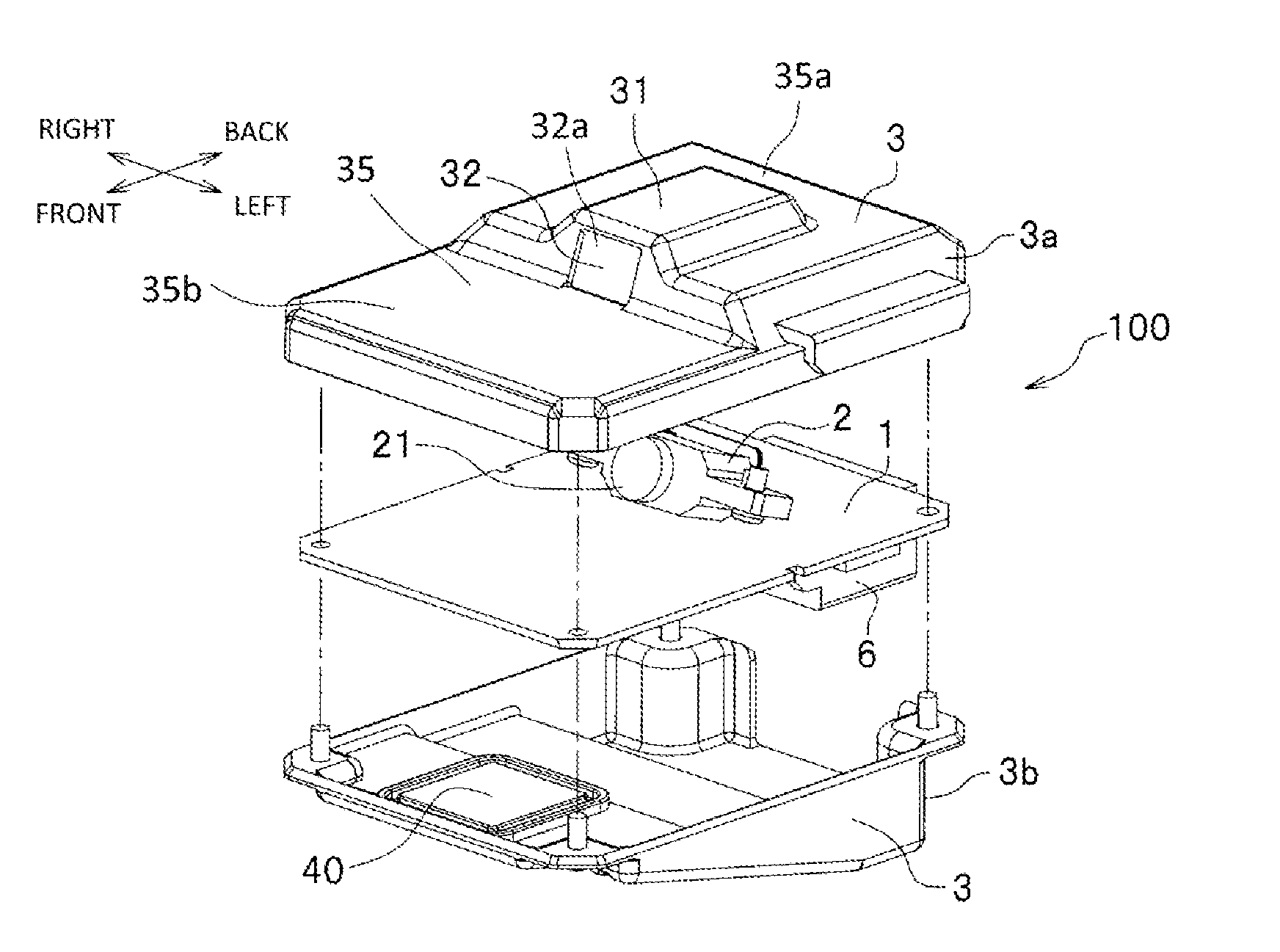
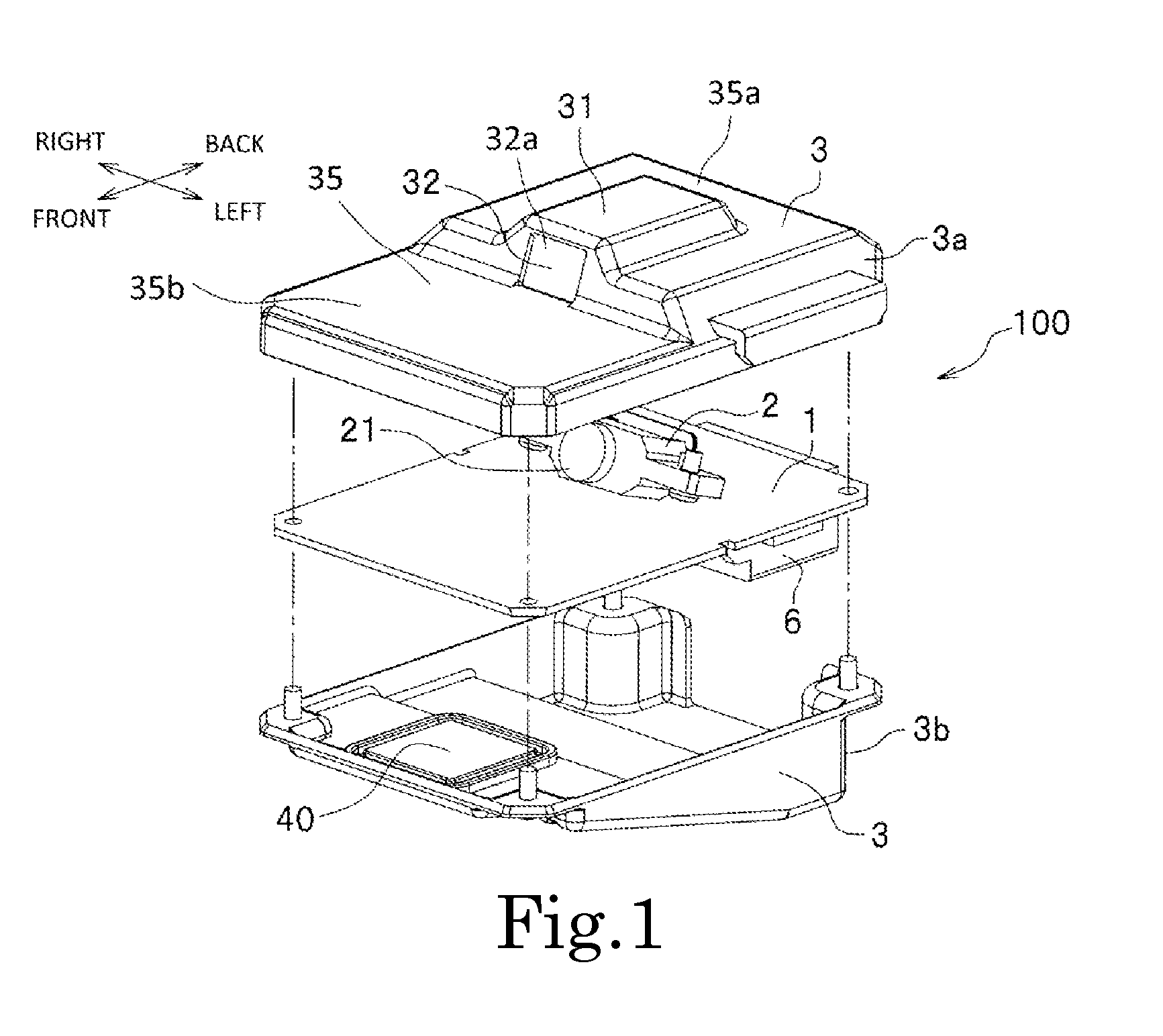
[0024]A housing (a vehicle-mounted camera housing) 3 according to a preferred embodiment of the present invention is a general-purpose housing for vehicle-mounted apparatuses that are configured to be attached to various car models. As shown in FIG. 1, in the present preferred embodiment, the housing 3 is included in a vehicle-mounted camera (a vehicle-mounted apparatus) 100.

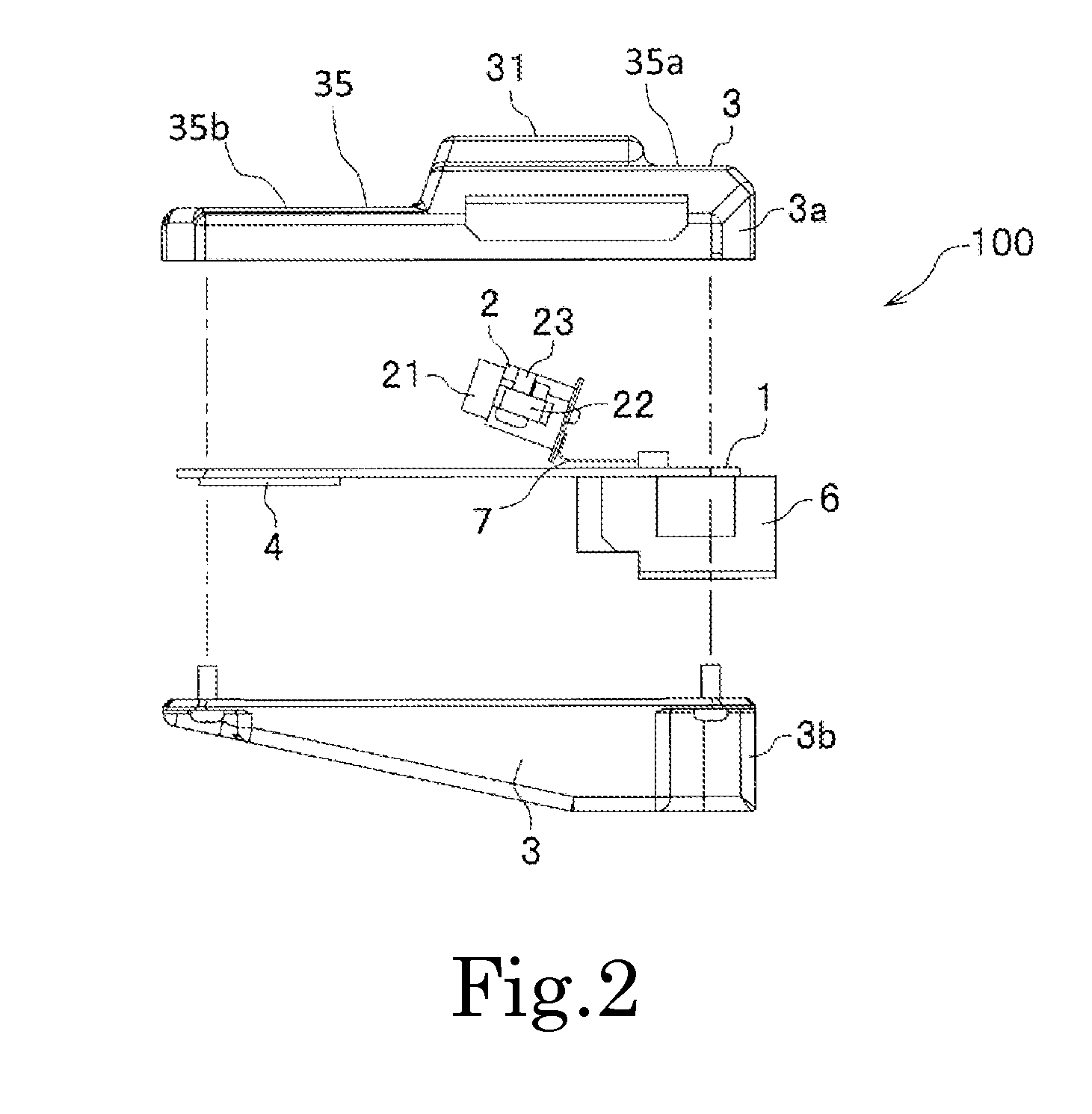
[0025]First, the overall configuration of the vehicle-mounted camera 100 is explained with reference to FIGS. 1 to 3.

[0026]As shown in FIGS. 1 to 3, the vehicle-mounted camera 100 picks up a video stream of images during traveling. The vehicle-mounted camera 100 includes a circuit board 1, a camera main body portion (a vehi...


PUM

PropertyMeasurementUnit
angleaaaaaaaaaa
angle θBaaaaaaaaaa
angleaaaaaaaaaa

Abstract

A method of manufacturing a vehicle-mounted camera housing including a cover housing, a camera main body and a circuit board includes providing a set of partial molds which are combined to form an internal cavity. When the combined partial molds are separated, an intermediate member is taken out and machined to obtain the cover housing. A top plate portion of the cover housing includes a pedestal extending downward. The machining includes cutting a distal end of the pedestal such that a flat face of the pedestal faces a predetermined direction with reference to an inclination angle of a windshield of a target vehicle, a relative direction of an optical axis of the camera, relative directions of the pedestal flat face and an upper surface of the top plate portion, and relative directions of the top plate and the windshield surface.

Description

BACKGROUND OF THE INVENTION[0001]1. Field of the Invention[0002]The present invention relates to a method of manufacturing a vehicle-mounted camera housing of a vehicle-mounted apparatus attached to various car models, a vehicle-mounted camera housing, and a vehicle-mounted camera.[0003]2. Description of the Related Art[0004]Conventionally, there has been used a vehicle-mounted camera that applies image processing to an image picked up by a camera attached to a vehicle to extract information regarding a traffic lane on a road surface, a preceding vehicle, an oncoming vehicle, a person, or a road sign from the image. The vehicle-mounted camera is used with a vehicle-mounted system that supports safe traveling of the vehicle and a monitoring system that monitors intrusion of suspicious persons.[0005]In recent years, a variety of sensors such as a rain sensor, an illuminance sensor, a millimeter wave or laser radar sensor have been mounted on vehicles. Therefore, an attachment space fo...

Claims


Application Information

Patent Timeline
Patent Type & Authority Applications(United States)
IPC IPC(8): H04N5/225G01B11/26B60R11/04H04N7/18G06T7/00
CPCH04N5/2252H04N7/183G06T7/004B60R11/04B60R2011/0026G06T2207/10004G06T2207/30252G06T2207/30256G01B11/26Y10T29/49002B22D17/06H04N23/51G06T7/001G03B17/02G03B17/12
Inventor TAKEDA, NAOYA
Owner NIDEC ELESYS
Why Eureka
Try Eureka