Surface modified unit cell lattice structures for optimized secure freeform fabrication

a technology of surface modified unit cells and freeform fabrication, applied in computer aided design, electric/magnetic/electromagnetic heating, instruments, etc., can solve the problems of potential site for debris generation, porous geometries are not supported by the underlying structure,

Active Publication Date: 2013-10-10
HOWMEDICA OSTEONICS CORP +1
View PDF1 Cites 169 Cited by
  • Summary
  • Abstract
  • Description
  • Claims
  • Application Information

AI Technical Summary

Problems solved by technology

Such truncation helps to achieve the near-net shape of the intended structure, but truncated or clipped struts may, in some instances, create a situation where the porous

Method used


Image

  • Surface modified unit cell lattice structures for optimized secure freeform fabrication
  • Surface modified unit cell lattice structures for optimized secure freeform fabrication
  • Surface modified unit cell lattice structures for optimized secure freeform fabrication

Examples


Embodiment Construction

[0042]This invention relates generally to generating computer models of three-dimensional structures. These models may be used to prepare porous tissue in-growth structures in medical implants and prostheses. The models may include features corresponding to tangible structures having nodes along a predefined outer boundary.

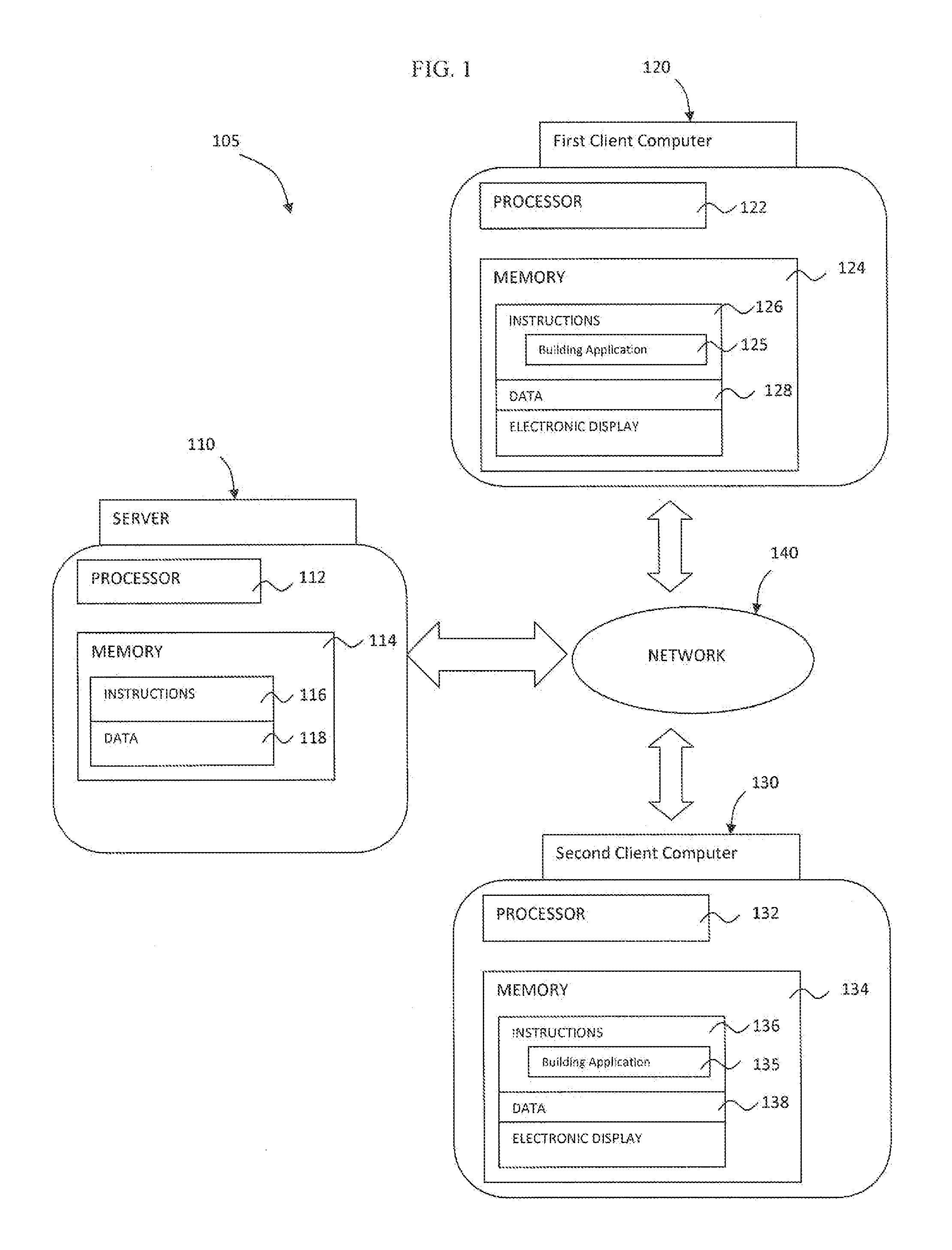
[0043]FIG. 1 depicts a system 105 that may be used, among other functions, to generate, store and share three-dimensional models of structures. The system 105 may include at least one server computer 110, a first client computer 120, and in some instances, at least a second client computer 130. These computers may send and receive information via a network 140. For example, a first user may generate a model at the first client device 120. The model may then be uploaded to the server 110 and distributed via the network 140 to the second client computer 130 for viewing and modification by at least a second user.

[0044]The network 140, and intervening communication po...


PUM

PropertyMeasurementUnit
Lengthaaaaaaaaaa
Structureaaaaaaaaaa
Electrical resistanceaaaaaaaaaa

Abstract

Aspects of the present disclosure relate generally to preparing models of three-dimensional structures. In particular, a model of a three-dimensional structure constructed of porous geometries is prepared. A component file including a porous CAD volume having a predefined portion of a boundary. A space including the porous CAD volume is populated with unit cells overlapping the predefined portion of the boundary. The unit cells are populated with porous geometries having a plurality of struts having nodes on each end. At least a first strut overlaps the predefined portion of the boundary and has a length, a first node outside the porous CAD volume, and a second node inside the porous CAD volume. All struts entirely outside the porous CAD volume are removed. After removal of the struts entirely outside the porous CAD volume, each of the remaining struts is connected to a node at each end thereof.

Description

FIELD OF THE INVENTION[0001]The present invention relates generally to preparing computer-generated models of porous structures. In particular, the surfaces of computer-generated models of structures may be modified through movement and removal of struts and nodes of porous geometries near the surface to produce surfaces conforming to the surfaces of intended physical structures being modelled.BACKGROUND OF THE INVENTION[0002]The field of free-form fabrication has seen many important recent advances in the fabrication of articles directly from computer controlled databases. These advances, many of which are in the field of rapid prototyping of articles such as prototype parts and mold dies, have greatly reduced the time and expense required to fabricate articles, particularly in contrast to conventional machining processes in which a block of material, such as a metal, is machined according to engineering drawings.[0003]One example of a modern rapid prototyping technology is a selec...

Claims


Application Information

Patent Timeline
IPC IPC(8): G06F17/50B29C35/08
CPCG06F17/50B33Y50/00G06F30/00
Inventor JONES, ERICSUTCLIFFE, CHRISTOPHER J.ROBINSON, JOEJONES, DANMULLEN, LEWIS
Owner HOWMEDICA OSTEONICS CORP
Why Eureka
Try Eureka