Apparatus and Method for Aligning a Guide Pin for Joint Re-Surfacing

a guide pin and joint technology, applied in the field of orthopedic surgery, can solve the problems of affecting the performance and procedure of the surgeon, the varus placement of the femoral component and notching during the surgery, and the surgery is more difficult and complication-free, and the effect of reducing the risk of fractur

Inactive Publication Date: 2009-05-07
KREUZER STEFAN
View PDF12 Cites 191 Cited by
  • Summary
  • Abstract
  • Description
  • Claims
  • Application Information

AI Technical Summary

Problems solved by technology

Although hip resurfacing arthroplasty removes less bone, it is a technically more difficult operation with a higher complication rate then routine total hip replacement.
Although BMI and gender of a given patient cannot be controlled by the surgeon, varus placement of the femoral component and notching during surgery may be impacted by the surgeon's performance and procedure.
Due to the subtleties involved with aligning version angle, the varus / valgus angle, and guide pin entry point during resurfacing operations due to numerous anatomical variations, most conventional drill guides are bulky, cumbersome and require alignment of all three dimensions simultaneously, which can be quite challenging and often requires repositioning the guide pin.

Method used


Image

  • Apparatus and Method for Aligning a Guide Pin for Joint Re-Surfacing
  • Apparatus and Method for Aligning a Guide Pin for Joint Re-Surfacing
  • Apparatus and Method for Aligning a Guide Pin for Joint Re-Surfacing

Examples


Embodiment Construction

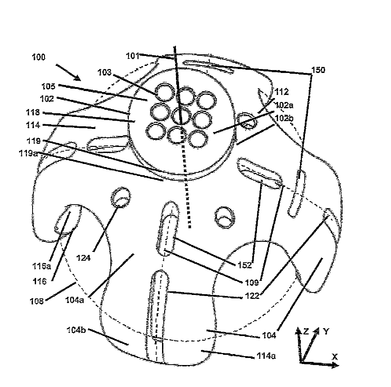
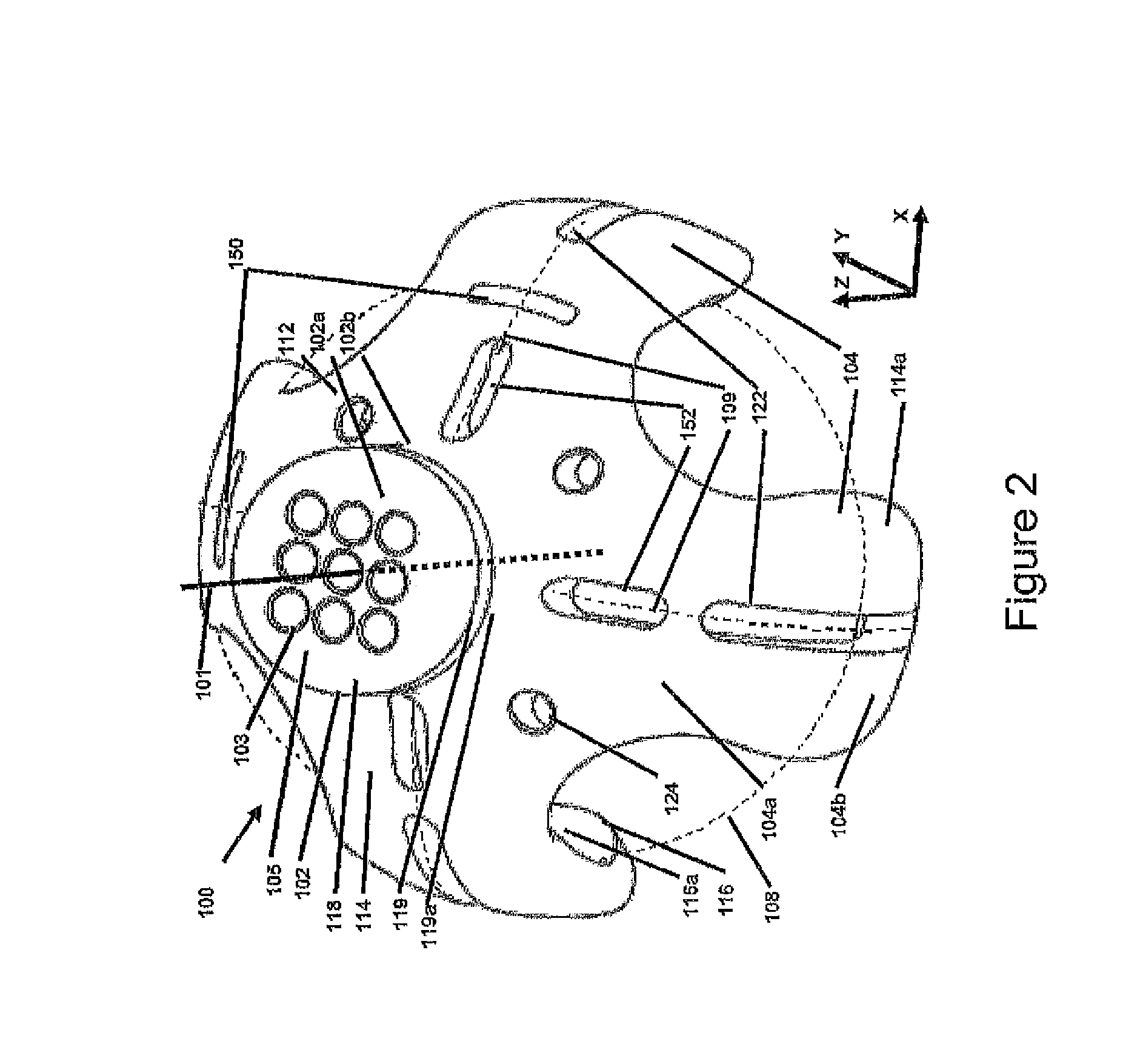
[0010]These and other needs in the art are addressed in one embodiment by a drill guide for aligning a guide pin. In an embodiment, the drill guide comprises a base having a concave inner surface, an outer surface opposite the inner surface, and a central axis perpendicular to the inner surface. In addition, the drill guide comprises a drilling template extending axially from the outer surface of the base along the central axis and includes a plurality of through-bores extending completely through the drilling template to the inner surface of the base. Further, the drill guide comprises a first curved member extending along a central longitudinal axis from a fixed end integral with the base to a free end distal the base and a second curved member extending along a central longitudinal axis from a fixed end integral with the base to a free end distal the base. The first curved member and the second curved member are angularly spaced about 180 degrees apart relative to the central axi...


PUM


Abstract

A drill guide for aligning a guide pin. In an embodiment, the drill guide comprises a base having a concave inner surface, an outer surface, and a central axis perpendicular to the inner surface. In addition, the drill guide comprises a drilling template extending axially from the outer surface of the base along the central axis. The drilling template includes a plurality of through-bores. Further, the drill guide comprises a first curved member extending along a central longitudinal axis from a fixed end integral with the base to a free end distal the base, and a second curved member extending along a central longitudinal axis from a fixed end integral with the base to a free end distal the base. The first curved member and the second curved member are angularly spaced about 180° apart relative to the central axis and include an elongate locking slot.

Description

CROSS-REFERENCE TO RELATED APPLICATIONS[0001]This application claims the benefit of U.S. provisional application Ser. No. 60 / 985,547, filed Nov. 5, 2007, and entitled “Joint Re-Surfacing Drill Guide”,” which is hereby incorporated herein by reference in its entirety.STATEMENT REGARDING FEDERALLY SPONSORED RESEARCH OR DEVELOPMENT[0002]Not Applicable.BACKGROUND[0003]1. Field of the Invention[0004]The invention relates generally to devices and methods for orthopedic surgery. More particularly, the invention relates to devices and method for aligning a guide pin for re-surfacing the ball portion of a ball and socket joint.[0005]2. Background of the Invention[0006]Total hip replacement, also referred to as hip arthroplasty, is a surgical procedure in which the hip joint is replaced by a prosthetic implant. Hip joint replacement surgery is typically conducted to relieve arthritis or to repair severe joint damage resulting from fracture. Hip resurfacing arthroplasty is a type of hip replac...

Claims


Application Information

Patent Timeline
Patent Type & Authority Applications(United States)
IPC IPC(8): A61B17/58
CPCA61B17/175
Inventor KREUZER, STEFAN
Owner KREUZER STEFAN
Why Eureka
Try Eureka