

Cargo rack
- Summary
- Abstract
- Description
- Claims
- Application Information
AI Technical Summary
Benefits of technology
Problems solved by technology
Method used
Image

Examples
Embodiment Construction
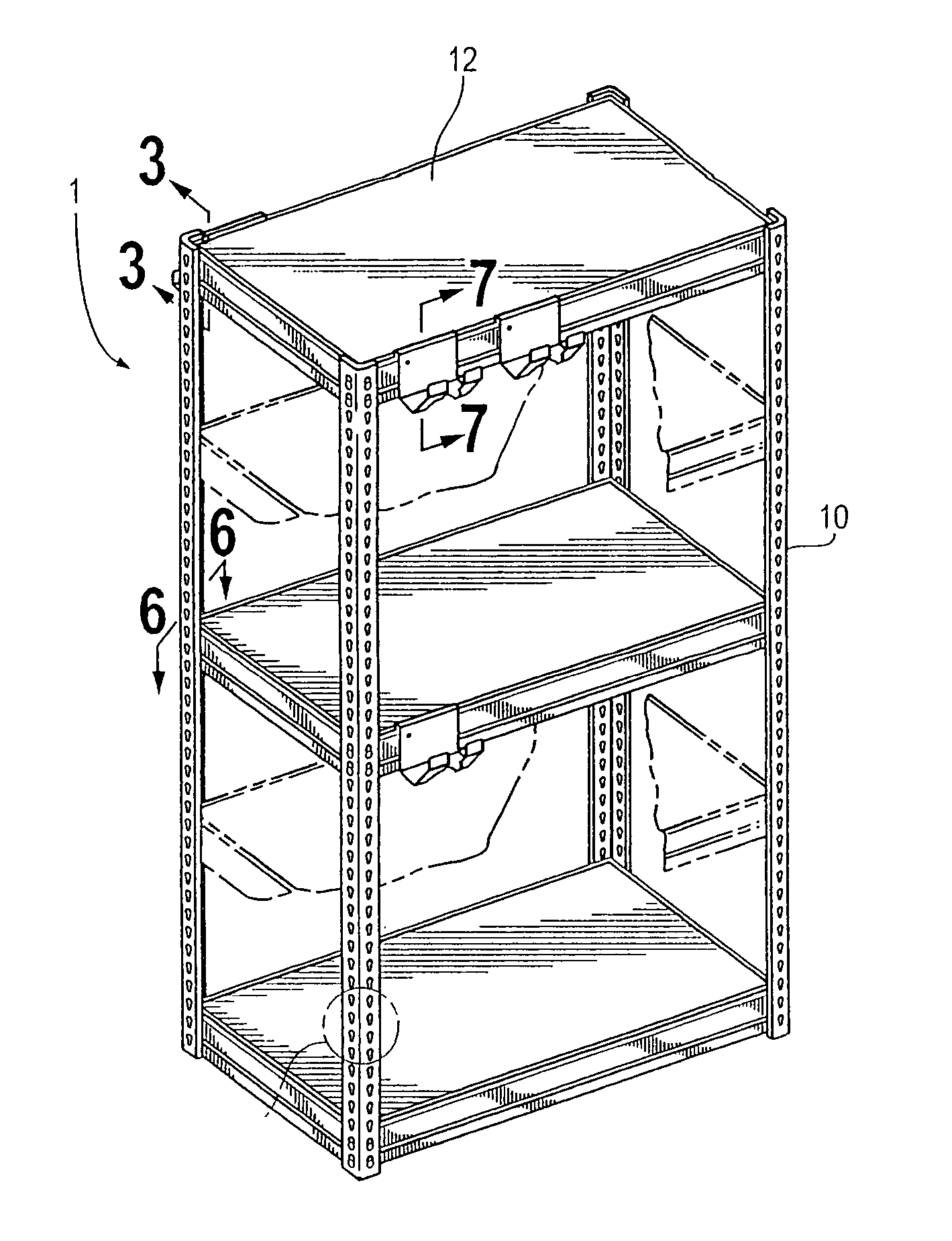
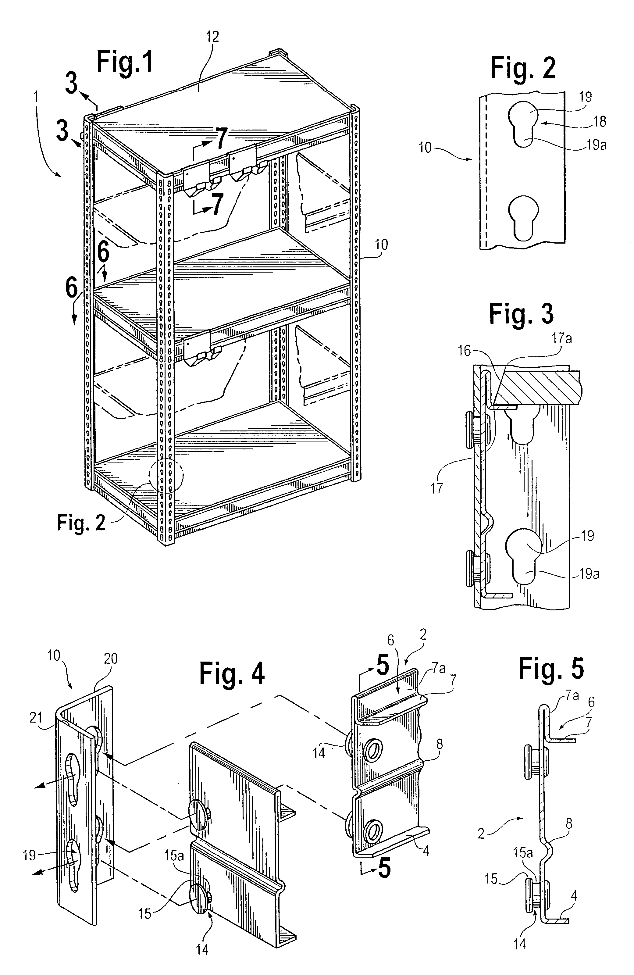
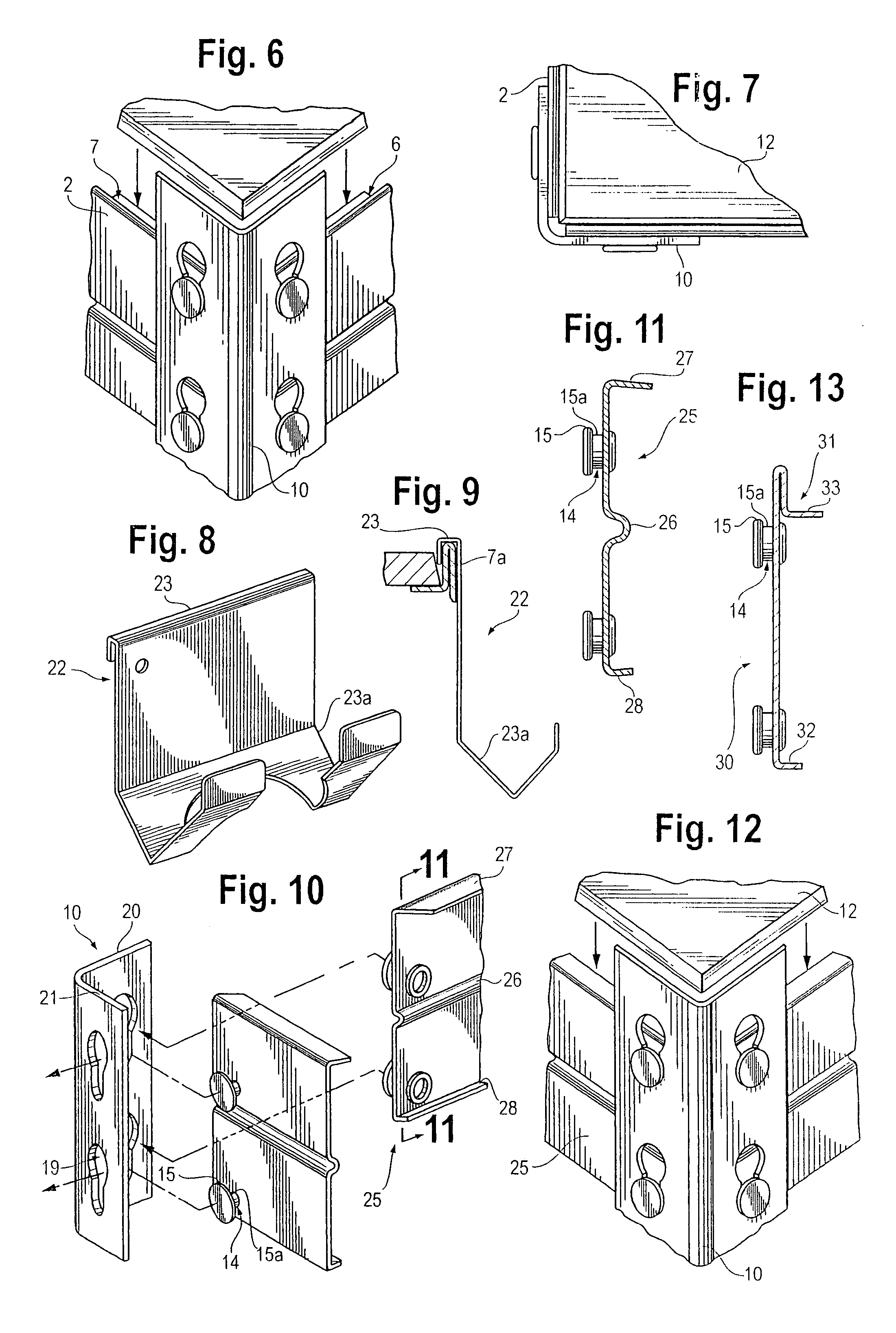
[0027] Referring to FIG. 1, the assembled shelving unit 1 is shown including four vertical posts 10. Each vertical post 10 has a pair of legs 20, 21 perpendicular to one another as shown in FIG. 14. As shown in FIGS. 1 and 14, a plurality of structural beams 50 and horizontal shelving members 12 extend between the pairs of legs 20, 21 on vertical posts 10 and may be attached in a manner that is described below.
[0028] The structural beams 50 contain circular apertures 51 which can be seen in FIG. 14. The purpose of circular apertures 51 are to provide means for the structural beams 50 to become associated with vertical posts 10. A pair of the circular apertures 51 are located at each end of structural beam 50. The vertical location of each pair of circular apertures 51 is relative to the vertical distance between the key shaped apertures 18 on legs 20 and 21 on vertical post 10. Furthermore, each pair of circular apertures 51 will be generally proportionate across the vertical cente...
PUM
 Abstract
Description
Claims
Application Information