Transverse rod connector clip

a connector clip and transverse rod technology, applied in the field of transverse rod connector clips, can solve the problems of irritating the patient's back muscles and other tissues, unable to achieve minimal torsional control, and inconvenient surgery

Inactive Publication Date: 2001-10-16
HOWMEDICA OSTEONICS CORP
View PDF49 Cites 192 Cited by
  • Summary
  • Abstract
  • Description
  • Claims
  • Application Information

AI Technical Summary

Problems solved by technology

These components provide the necessary stability both in tension and compression yet yield minimal torsional control.
However, this configuration is bulky and can cause irritation of the patient's back muscles a...

Method used


Image

  • Transverse rod connector clip
  • Transverse rod connector clip
  • Transverse rod connector clip

Examples


Embodiment Construction

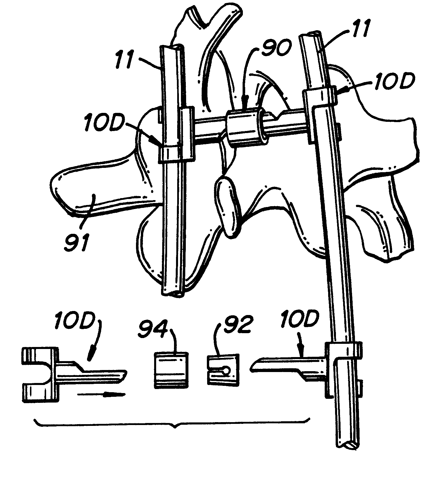
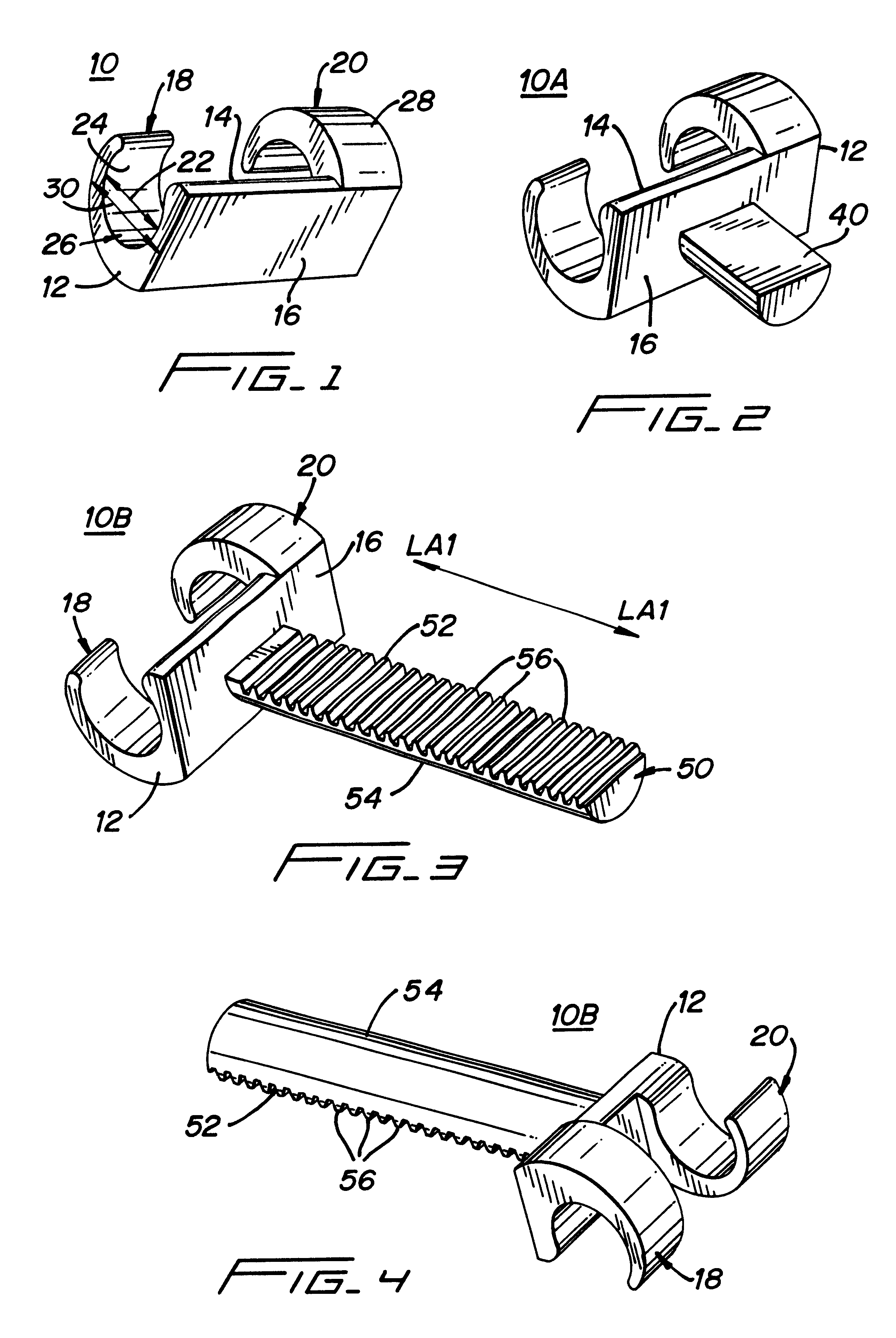
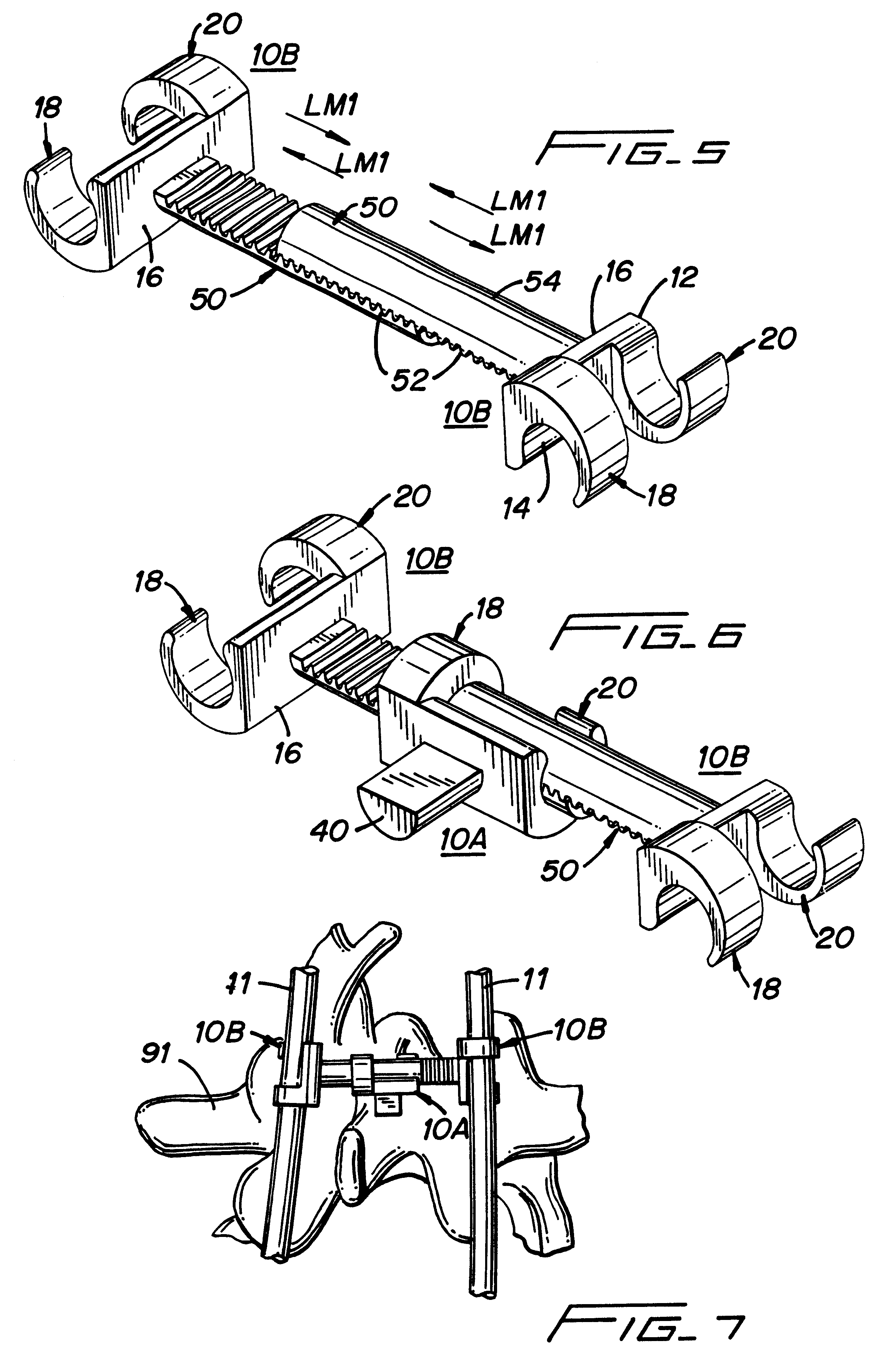
The present invention is directed to a transverse connector clip 10 and assemblies used in spinal fixation systems. Spinal fixation systems typically include spinal instrumentation having connective structures such as a pair of plates and / or rods which are placed on opposite sides of the spinal column near vertebrae that are intended to be fused. These spinal systems consist of screws and hooks for segmental attachment to the spine and longitudinal rods connected to screws or hooks. These components provide the necessary stability both in tension and compression yet yield minimal torsional control. In addition, it has been found that when a pair of spinal rods are fastened in parallel on either side of the spinous process, the assembly can be significantly strengthened by using at least one additional rod to horizontally bridge the pair of spinal rods.

The transverse connector clips 10 of the present invention consist of a component with a means to clip the device on a spinal or cyli...


PUM


Abstract

A transverse connector clip for connecting cylindrical rods to each other in a spinal fixation system, comprising a clip body having two sides. The first side of the clip body has a longitudinal axis and a pair of mirror image hemi-cylindrical shells. These hemi-cylindrical shells have an inner diameter that is slightly smaller than the outer diameter of a cylindrical rod. The clip body is shaped so as to allow the hemi-cylindrical shells to spread around the cylindrical rod when the cylindrical rod is inserted between said shells and to securely clamp on the cylindrical rod at a 90° angle relative to the clip body The second side of the clip body can comprise one of several embodiments; a short laterally extending hemi-cylinder rod, a laterally extending hemi-cylinder rod with a plurality of vertical teeth, a second pair of mirror image hemi-cylindrical shells, a laterally extending rod tapering from a proximal cylindrical shape to a distal hemi-cylinder shape, or a body portion and a locking mechanism configured to receive and lock a hemi-cylindrical or cylindrical rod.

Description

1. Field of the InventionThe present invention relates to implantable spinal fixation systems for the surgical treatment of spinal disorders. More particularly, this invention relates to a transverse rod connector clip for connecting cylindrical rods to each other.2. Background of the InventionFor years doctors attempted to restore stability to the spine by fusion (arthrodesis) of the problem area. This treatment yielded marginal results due to the inherently flexible spinal column. Over the past ten years spinal implant systems have been developed to add stability to the spine to enhance the arthrodesis rates. Such systems often include spinal instrumentation having connective structures such as a pair of plates and / or rods which are placed on opposite sides of the portion of the spinal column which is intended to be fused. These spinal systems consist of screws and hooks for segmental attachment to the spine and longitudinal rods connected to screws or hooks. These components prov...

Claims


Application Information

Patent Timeline
IPC IPC(8): A61B17/70A61B17/58
CPCA61B17/7052
Inventor LIN, CHIH-INICHOLS, DAVID
Owner HOWMEDICA OSTEONICS CORP
Why Eureka
Try Eureka