Offshore Cable Laying Method

a cable laying and offshore technology, applied in the direction of cable laying apparatus, cable installation on float, electric cable installation, etc., can solve the problems of significant limitations and methods that have significant limitations

Active Publication Date: 2014-05-15
J RAY MCCDERMOTT SA
View PDF0 Cites 13 Cited by
  • Summary
  • Abstract
  • Description
  • Claims
  • Application Information

AI Technical Summary

Problems solved by technology

This method has significant limitations (especially with relatively large diameter, heavy cables), including effects of weather, currents, and lack of water depth for the buoyancy to be effective.
This method also requires the mother ship to come relatively close in to the shore (usually, about one kilome

Method used


Image

  • Offshore Cable Laying Method
  • Offshore Cable Laying Method
  • Offshore Cable Laying Method

Examples


Embodiment Construction

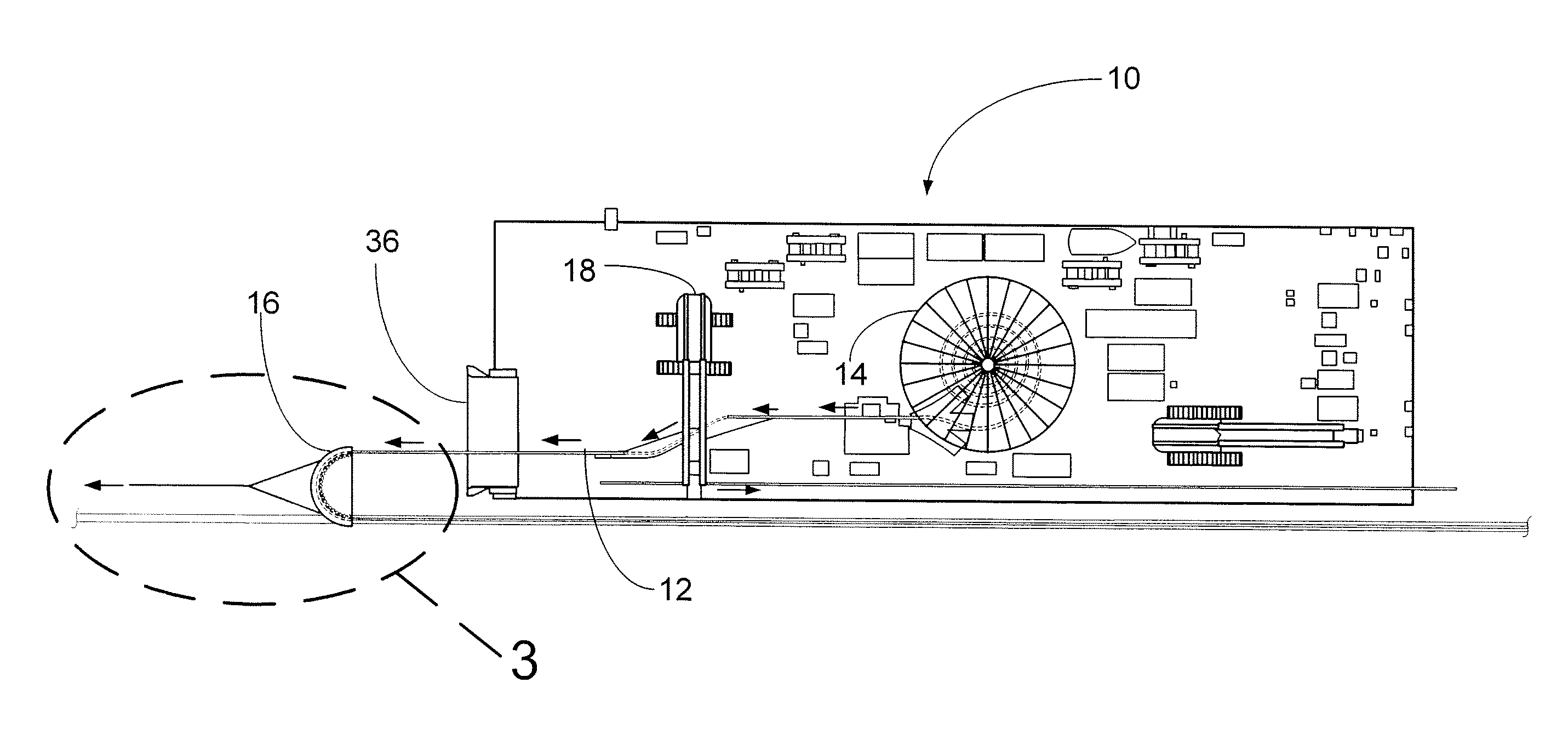
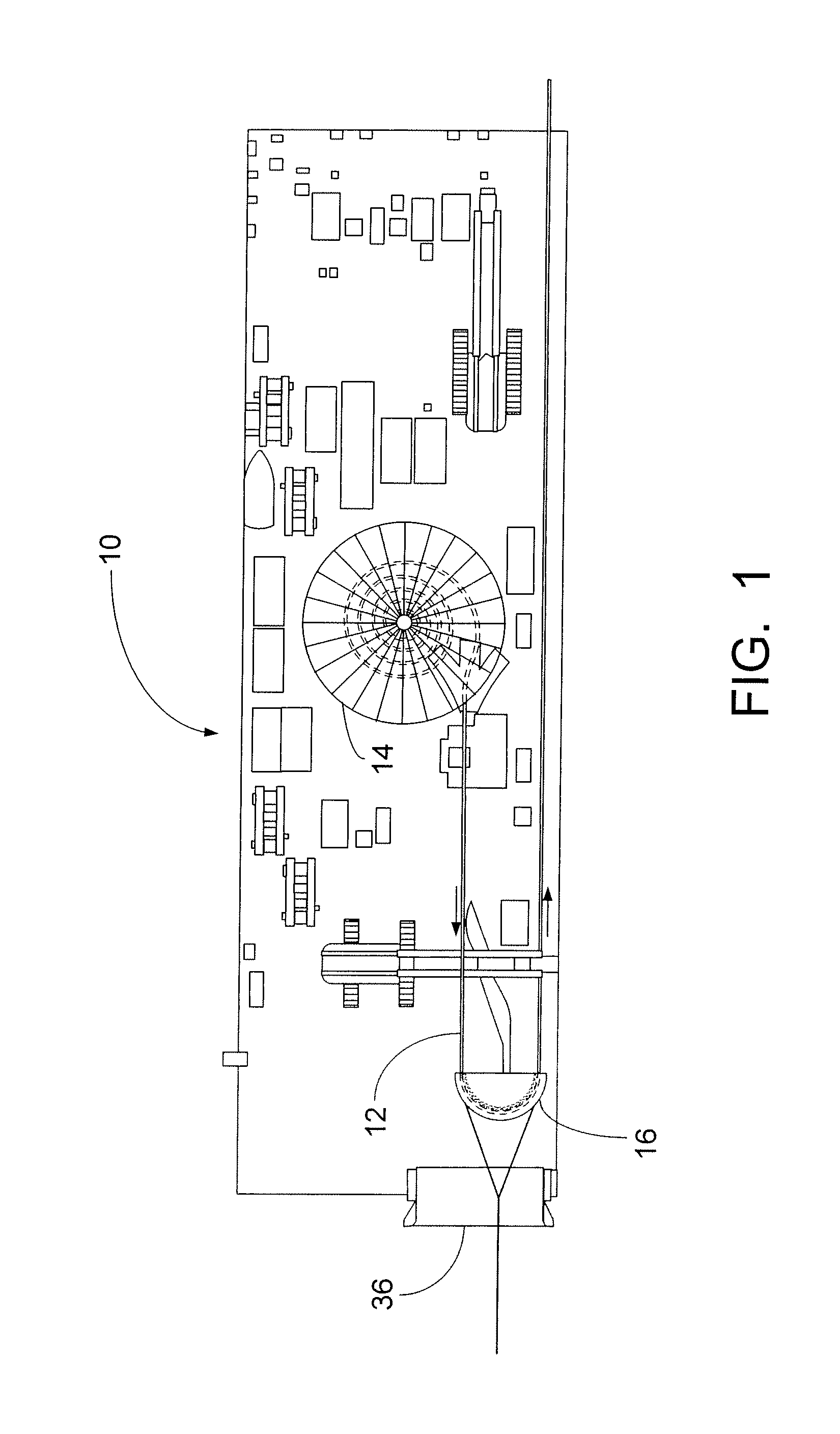
[0014]FIG. 1 is a plan view of a cable lay barge 10 that has been moved as close as possible to shore while laying cable. The barge 10 has reached the shallowest water depth possible and the remainder of the cable 12 to be laid and brought on shore is preferably in the carousel 14 on the barge 10.

[0015]It should be understood that the term “cable” as it is used herein is intended to mean any flexible pipe or cable-like product that is coiled in a carousel, basket or on a reel and required to be laid along a route between an offshore location and on-shore location. This can typically be any of all of the following:[0016]flexible pipe or flowline for conveying fluids;[0017]umbilical containing multiple cores for conveying different services including power, hydraulic, chemical and fiber optic transmissions;[0018]composite cable for power transmission and other services including fiber optic communication lines.

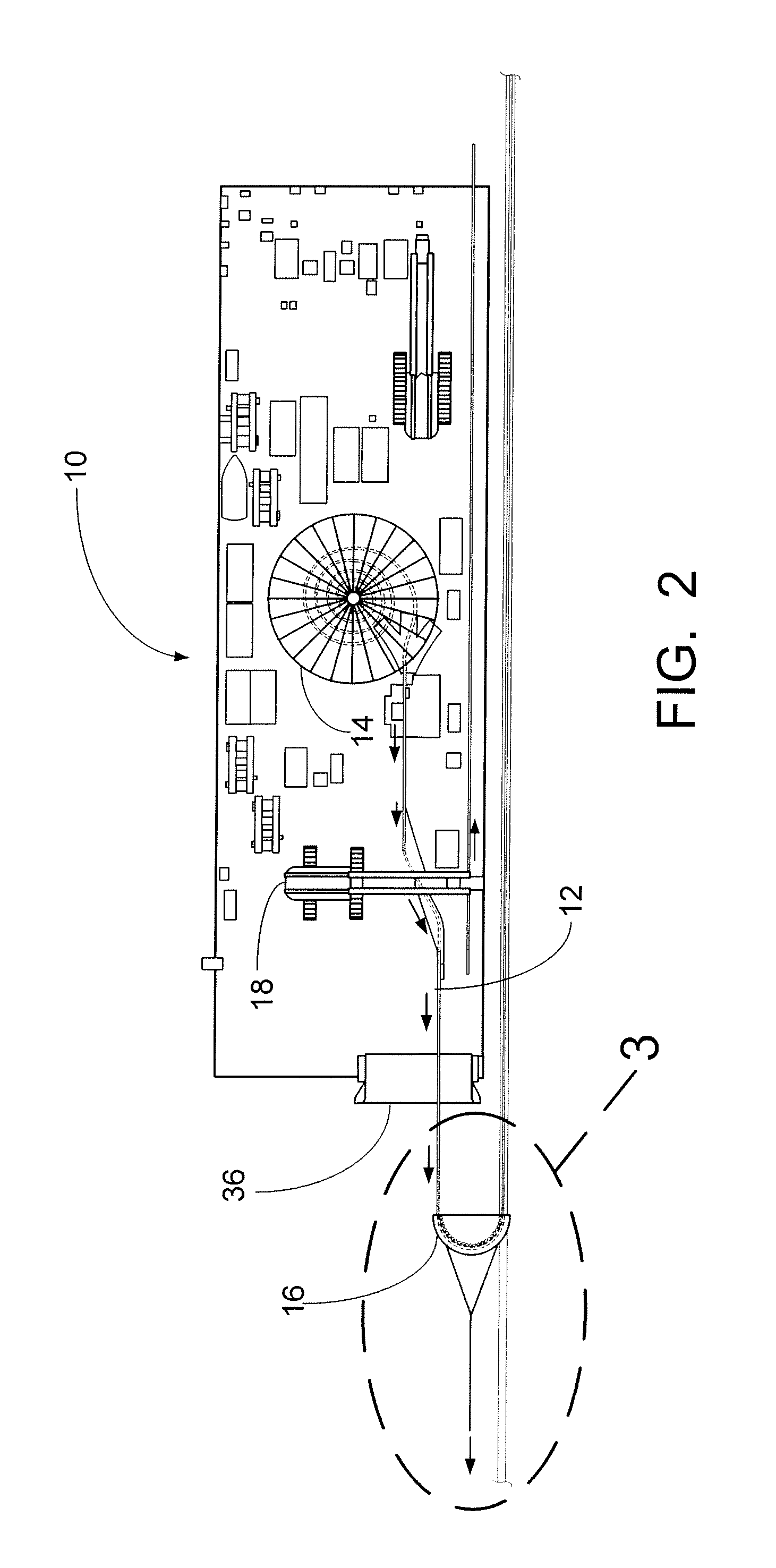
[0019]As seen in FIG. 2, the roller quadrant 16 has been lifted from the de...


PUM


Abstract

A method for laying cable from a vessel at a near shore location in shallow water to shore. The cable on the vessel is wrapped around a modified roller quadrant on the vessel. The roller quadrant is moved from the vessel into the water. A pulling device is attached by a line to the roller quadrant. The pulling device is used to pull the roller quadrant and cable toward shore. The pulling device may be positioned in the water and moved to shore as required. The pulling device may also be initially positioned on shore. The roller quadrant may include a skid and buoyancy modules to reduce the pulling force required to move the roller quadrant and lay the cable to shore.

Description

FIELD AND BACKGROUND OF INVENTION[0001]The invention is generally related to laying cable from a vessel and more particularly to laying cable to or from shore.[0002]Traditionally, the standard methodology for laying a subsea cable to or from shore would be by either of the following two methods.[0003]In the first method, a cable lay vessel (CLV) loaded with the full length of cable sets up at a distance from the shore ready to pay out the cable end. A winch wire from shore is connected to the cable end and begins pulling the cable towards the shore. Floatation buoys are attached at intervals as the cable is progressively paid out towards the shore. This method has significant limitations (especially with relatively large diameter, heavy cables), including effects of weather, currents, and lack of water depth for the buoyancy to be effective. This method also requires the mother ship to come relatively close in to the shore (usually, about one kilometer, maximum distance from shore) ...

Claims


Application Information

Patent Timeline
IPC IPC(8): H02G1/10
CPCH02G1/10H02G9/02H02G9/12
Inventor ANDERSON, THOM CHARLESFRASER, COLIN JAMES
Owner J RAY MCCDERMOTT SA
Why Eureka
Try Eureka