Toroidal variable speed traction drive

Active Publication Date: 2014-05-15
ULTIMATE TRANSMISSIONS
View PDF4 Cites 2 Cited by
  • Summary
  • Abstract
  • Description
  • Claims
  • Application Information

AI Technical Summary

Problems solved by technology

It must be understood that when the rollers are clamped between the discs with a large force it is not practical to simply slide them across the face of the discs in order to create a new ratio.
The Half Toroid designs operate a similar arrangement but for other mechanical reasons cannot use a castor angle.
Feedback loops are always subject to over-running targets resulting in oscillations or hunting.
Complex dampening systems are often required to eliminate such oscillations that are unacceptable in most transmission applications.
It is not theoretically possible for the rollers 1

Method used


Image

  • Toroidal variable speed traction drive
  • Toroidal variable speed traction drive
  • Toroidal variable speed traction drive

Examples


Embodiment Construction

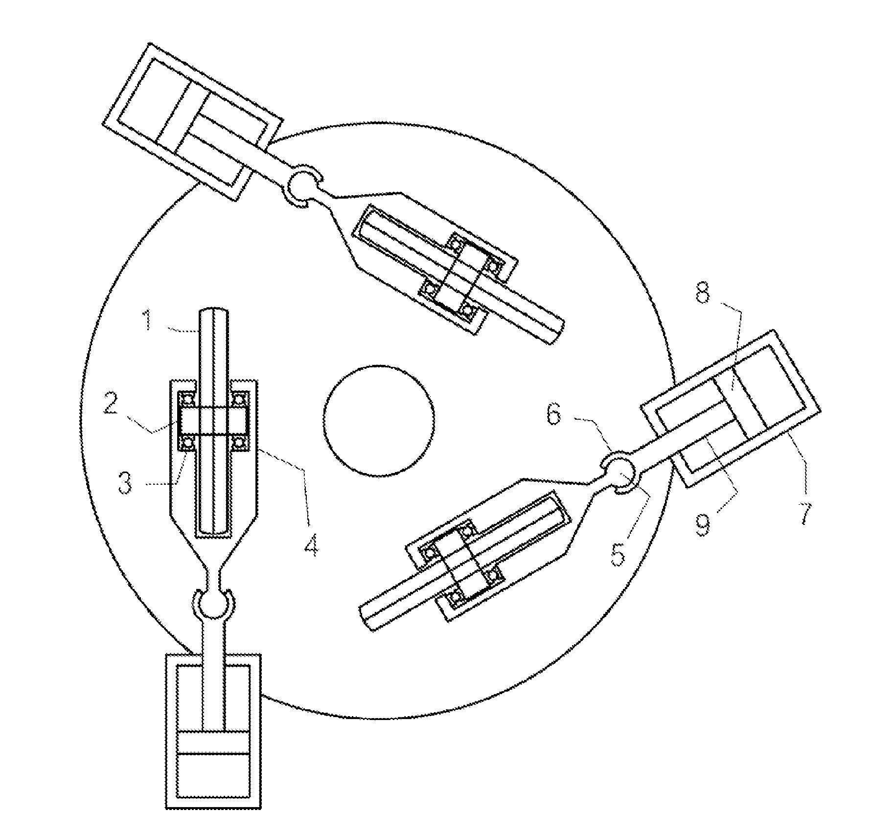
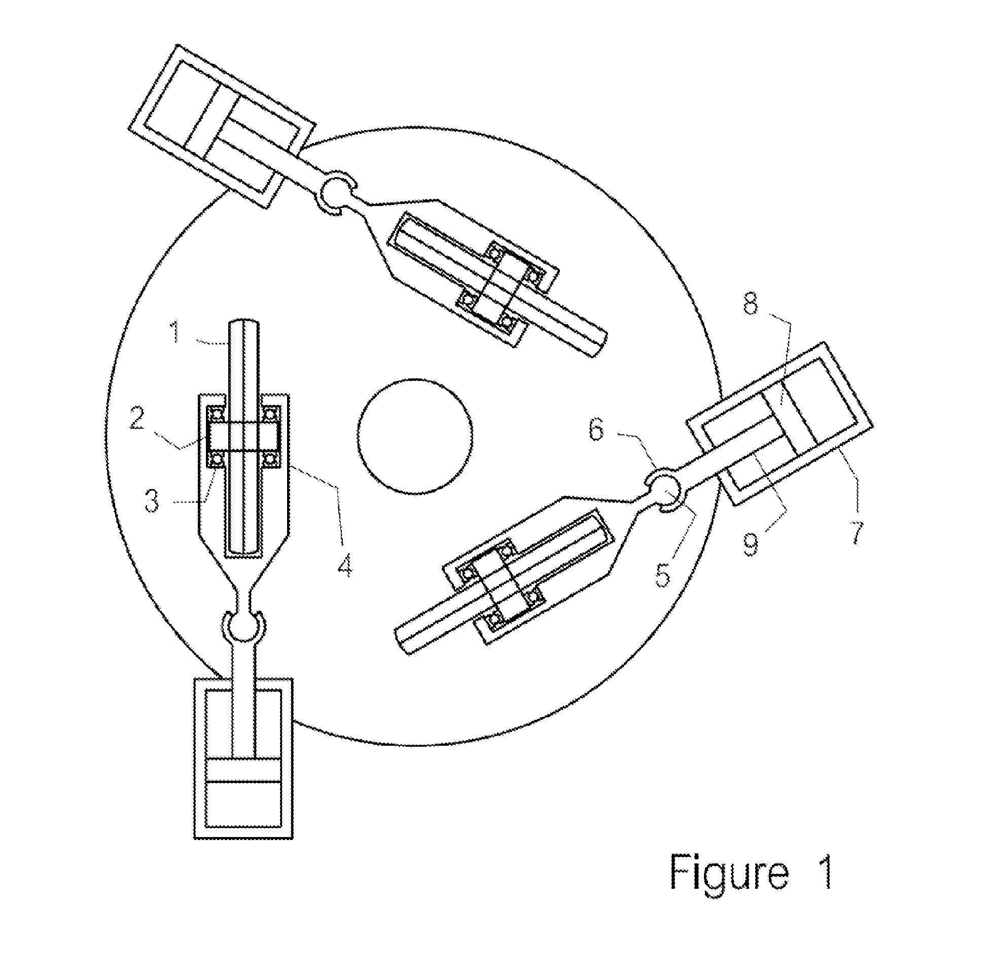
[0053]In a first particular embodiment of the invention three single rollers are arranged within a typical toroidal cavity as with the previously mentioned prior art.

[0054]FIG. 3 shows a plan view of such an arrangement in which the rollers 1 are mounted on an axle 2 on bearings 3 and held in a yoke 4, as before. At one end of the yoke is a ball 5 that is captured inside a ball enclosure 27. The ball enclosure is mounted inside one end of a trunnion 28.

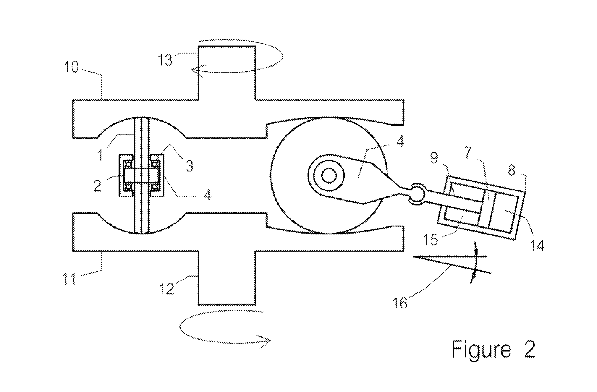
[0055]The trunnion 28 is formed at each end with an axle 29 and 30 which is mounted within a body enclosure 38 so that the trunnion 28 is free to rotate. The centre axis of the trunnion 28 passes through the centre of the toroidal cavity.

[0056]It can readily be seen that there is no mechanical restraint on the angle through which the roller 1 can rotate to create different ratios. For this reason it is possible to create ratio spreads of over 20:1. Also for this reason it is possible to place the rollers 1 a large distance from the ce...


PUM


Abstract

A toroidal variable speed traction drive is provided. The drive includes a driving disc and a driven disc. The discs have a common axis of rotation. The inner face of each disc is formed with a negative shape of a toroid. The drive further includes a plurality of roller assemblies interposed between the discs, each roller assembly including a roller. The discs are urged together against the interposed roller assemblies by a clamping force. Each roller assembly being connected to a corresponding rotatable trunnion. The trunnion applies a steering force to the corresponding roller assembly at a point relative to the corresponding roller assembly; the applied steering force causing the roller of the corresponding roller assembly to steer and adopt different contact points. The point at which the steering force is applied is located offset from the trunnion rotational axis at a fixed distance.

Description

TECHNICAL FIELD[0001]The present invention relates to Continuously Variable Transmissions, particularly of the Full Toroidal Race Rolling Traction Drive type with particular reference to the methods and arrangements for changing the ratio by roller steering.BACKGROUND OF THE INVENTION[0002]There are several Constantly Variable Transmissions (CVTs) that are being successfully designed and manufactured as transmissions for vehicles and other machines that require changing gear ratios.[0003]The market is supplied generally by Hydro-mechanical CVT's and traction based CVT's.[0004]Two major types of traction drives are used, although there are also many other proposals. One uses a belt running between adjustable pulley sheaves and the other a roller that runs between two discs with the negative shape of a toroid machined into it, generally called toroidal variators.[0005]This invention is related to toroidal variators and the control of the rollers within them.[0006]The toroidal drive ma...

Claims


Application Information

Patent Timeline
IPC IPC(8): F16H15/04
CPCF16H15/04F16H15/38F16H63/065F16H2015/383F16H15/48F16H15/52F16H15/44
Inventor DURACK, MICHAEL JAMES
Owner ULTIMATE TRANSMISSIONS
Why Eureka
Try Eureka