Portable punch device

a punching device and portability technology, applied in the field of punching devices, can solve the problems of requiring a large amount of force to punch a design in the materials to be manipulated, affecting the quality of the material being manipulated, so as to achieve the effect of reducing the degree of tolerance, quick and easy change of designs, and reducing the force of the punching action

Inactive Publication Date: 2006-01-19
OY FISKARS AB
View PDF9 Cites 1 Cited by
  • Summary
  • Abstract
  • Description
  • Claims
  • Application Information

AI Technical Summary

Benefits of technology

[0008] It is another object of the present invention to provide an improved portable punch device that permits a user to quickly and easily change the designs that are to be punched using the device.
[0009] It is still another object of the present invention to provide an improved portable punch device that enables a user to exert a higher level of force for the punching action than occurs using conventional punch devices.
[0010] It is yet another object of the present invention to provide an improved portable punch device that can be assembled with a lower degree of tolerance than conventional punch devices.
[0011] It is still another object of the present invention to provide an improved portable punch device that is relatively simple to manufacture.
[0012] It is finally another object of the present invention to provide an improved portable punch device that can be used on a wide variety of surfaces.

Problems solved by technology

Although such devices are widely used, they suffer from a number of a significant drawbacks.
As a result, a relatively high level of tolerance is required during the manufacturing and assembly process, adding to the assembly costs.
Additionally, such hand-held devices can require a high amount of force to punch a design in the materials to be manipulated.
This can create difficulties for people such as the elderly and young children, who may have difficulty “squeezing” the handles together.
Therefore it often requires a significant amount of force both to remove a die already in the device and to insert a new die.
The amount of force required can cause significant problems for many people such as children and the elderly.
This can create difficulties in accurately locating the punch device on the material for the punch.

Method used


Image

  • Portable punch device
  • Portable punch device
  • Portable punch device

Examples


Embodiment Construction

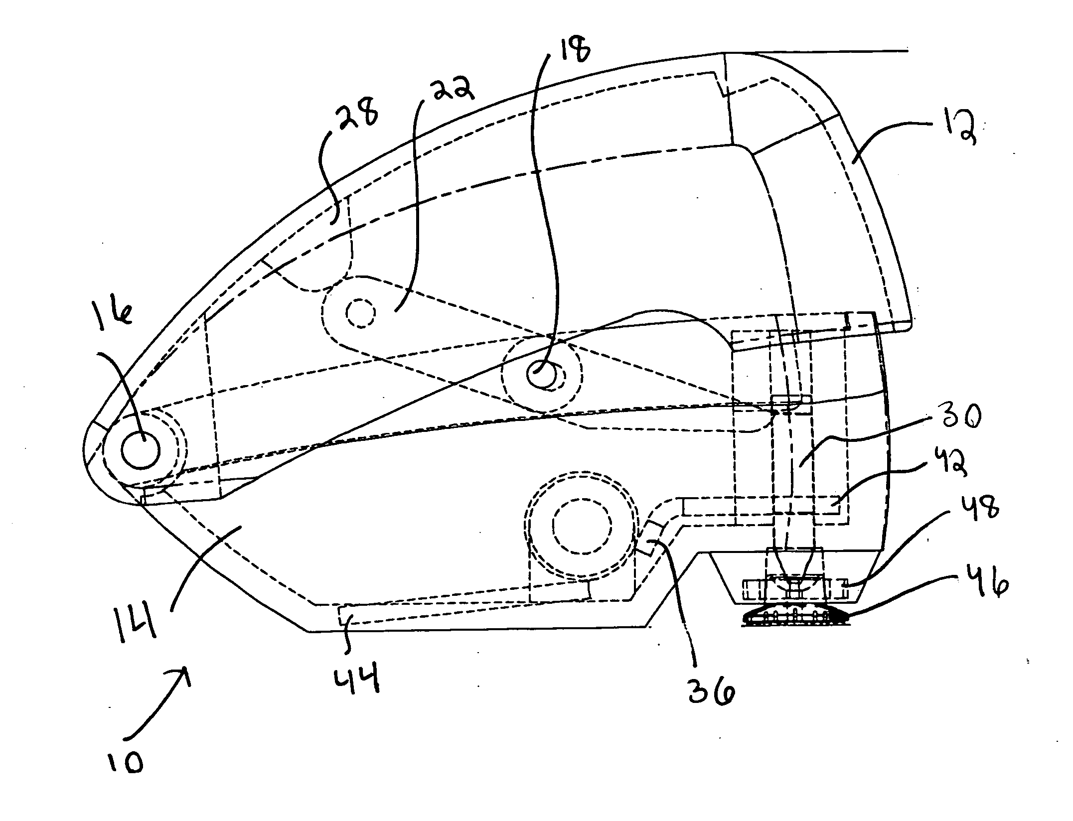
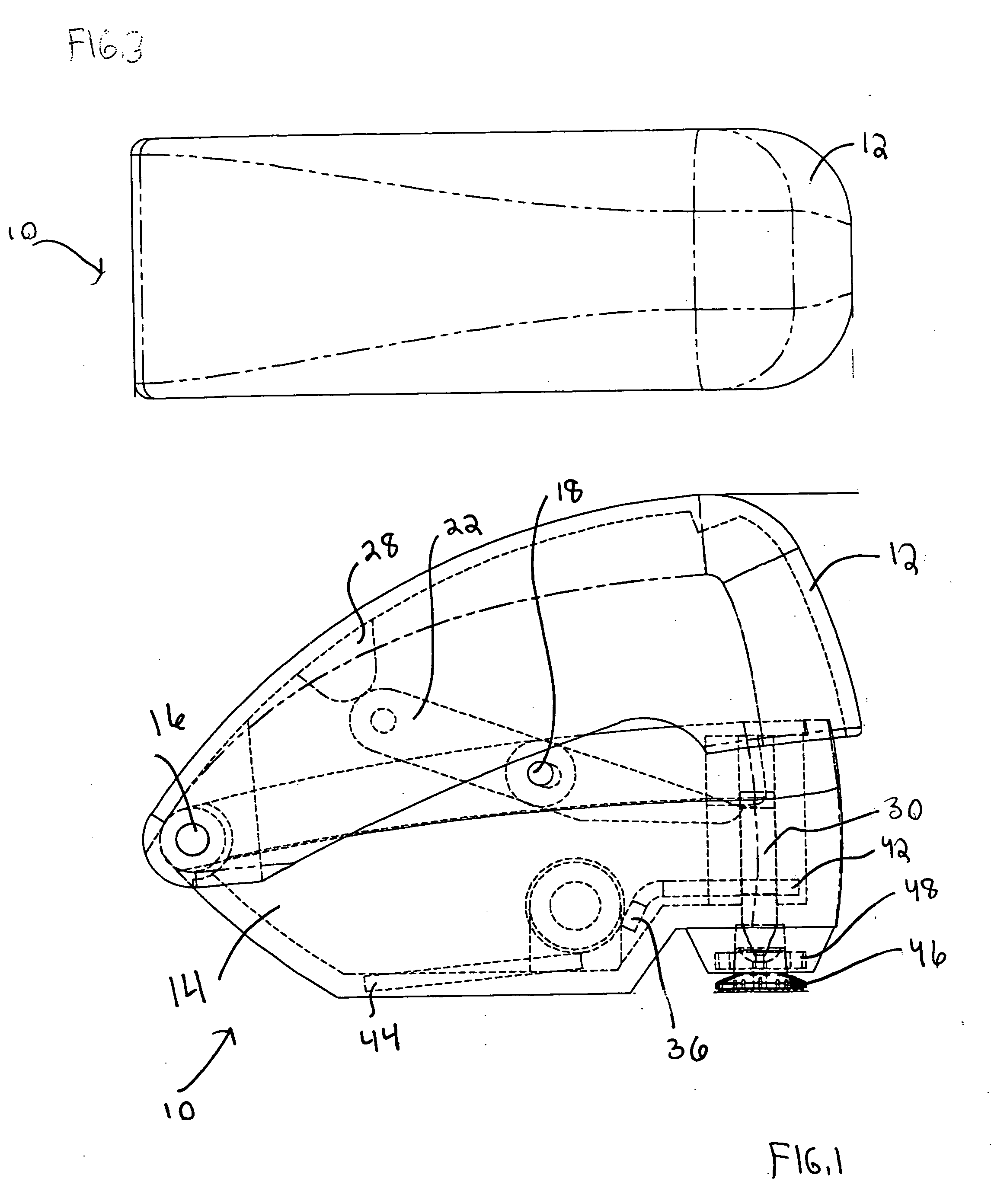
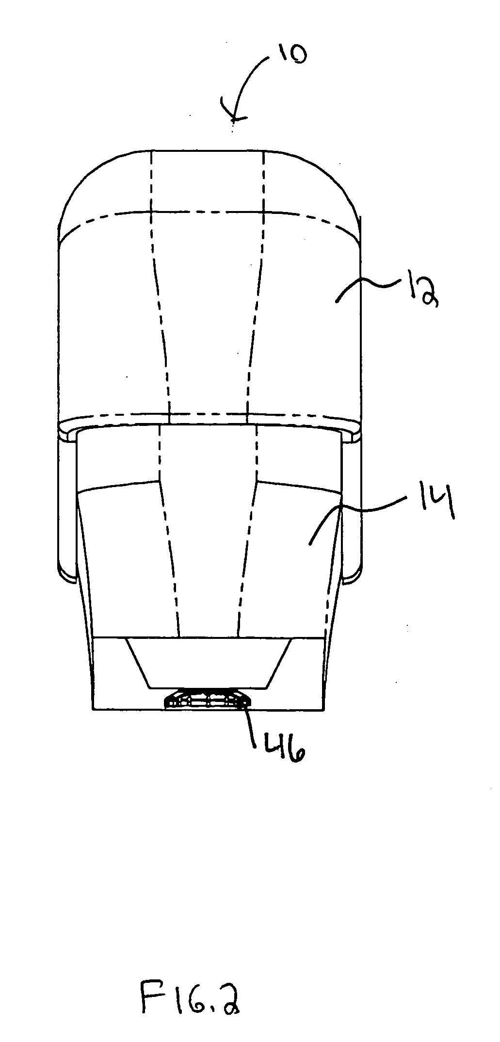
[0021] A punch assembly constructed according to the principles of the present invention is shown generally at 10 in FIGS. 1-5. The punch assembly 10, constructed according to one embodiment of the present invention, comprises an upper housing 12 and a lower housing 14. The lower housing 14 includes a rear pivot member 16 and an front pivot member 18. The upper housing 12 is coupled to the lower housing 14 at the rear pivot member 16 by a rear pivot pin 20. The rear pivot pin 20 permits the upper housing 12 to rotate relative to lower housing 14.

[0022] The punch assembly 10 includes a lever arm 22 that is rotatably coupled to the front pivot member 18 by a front pivot pen 24. The lever arm 22 is also operatively connected to a lever arm biasing member 26 which is positioned about the front pivot member 18. In the embodiment shown in FIGS. 1-5, the lever arm biasing member 26 comprises a coil spring. However, various other conventional biasing members may also be used. The rear end ...


PUM

PropertyMeasurementUnit
forceaaaaaaaaaa
shapesaaaaaaaaaa
distanceaaaaaaaaaa

Abstract

A punch device, comprising a lower housing and an upper housing pivotally connected to the lower housing. An impactor is positioned within the lower housing for selective action against a die, and at least one biasing member is positioned to bias the impactor towards the die. A lever arm selectively engaging the impactor and in contact with the upper housing. Actuation of upper housing causes the lever arm to move the impactor away from the die until the impactor disengages from the impactor and Upon disengagement, the impactor moves to towards the die so as to impart a force against the die.

Description

BACKGROUND OF THE INVENTION [0001] The present invention relates generally to punch devices. More particularly, the present invention is related to portable punch devices for creating patterns in materials such as paper and cardstock. [0002] A wide variety of mechanisms are conventionally known for cutting various shapes into materials such as paper, cardstock and vellum. For example, there are several hand held devices comprising a pair of handles and die members that permit a user to “punch” a design into a piece of material simply by squeezing the handles. [0003] Although such devices are widely used, they suffer from a number of a significant drawbacks. For example, these devices often rely upon a proper alignment between mating die members to effectuate the punch. As a result, a relatively high level of tolerance is required during the manufacturing and assembly process, adding to the assembly costs. Additionally, such hand-held devices can require a high amount of force to pun...

Claims


Application Information

Patent Timeline
Patent Type & Authority Applications(United States)
IPC IPC(8): B26D5/08
CPCB26F1/36B26F1/32Y10T83/869
Inventor SCHULZ, WILLIAM J.
Owner OY FISKARS AB
Why Eureka
Try Eureka