

Diaphragm actuator and method for producing a diaphragm actuator
a diaphragm actuator and actuator technology, applied in the direction of generator/motor, piezoelectric/electrostrictive transducer, transducer type, etc., can solve the problems of wasting requiring a lot of space, and achieve the effect of significantly reducing the space requirement of the diaphragm actuator
- Summary
- Abstract
- Description
- Claims
- Application Information
AI Technical Summary
Benefits of technology
Problems solved by technology
Method used
Image

Examples
second embodiment
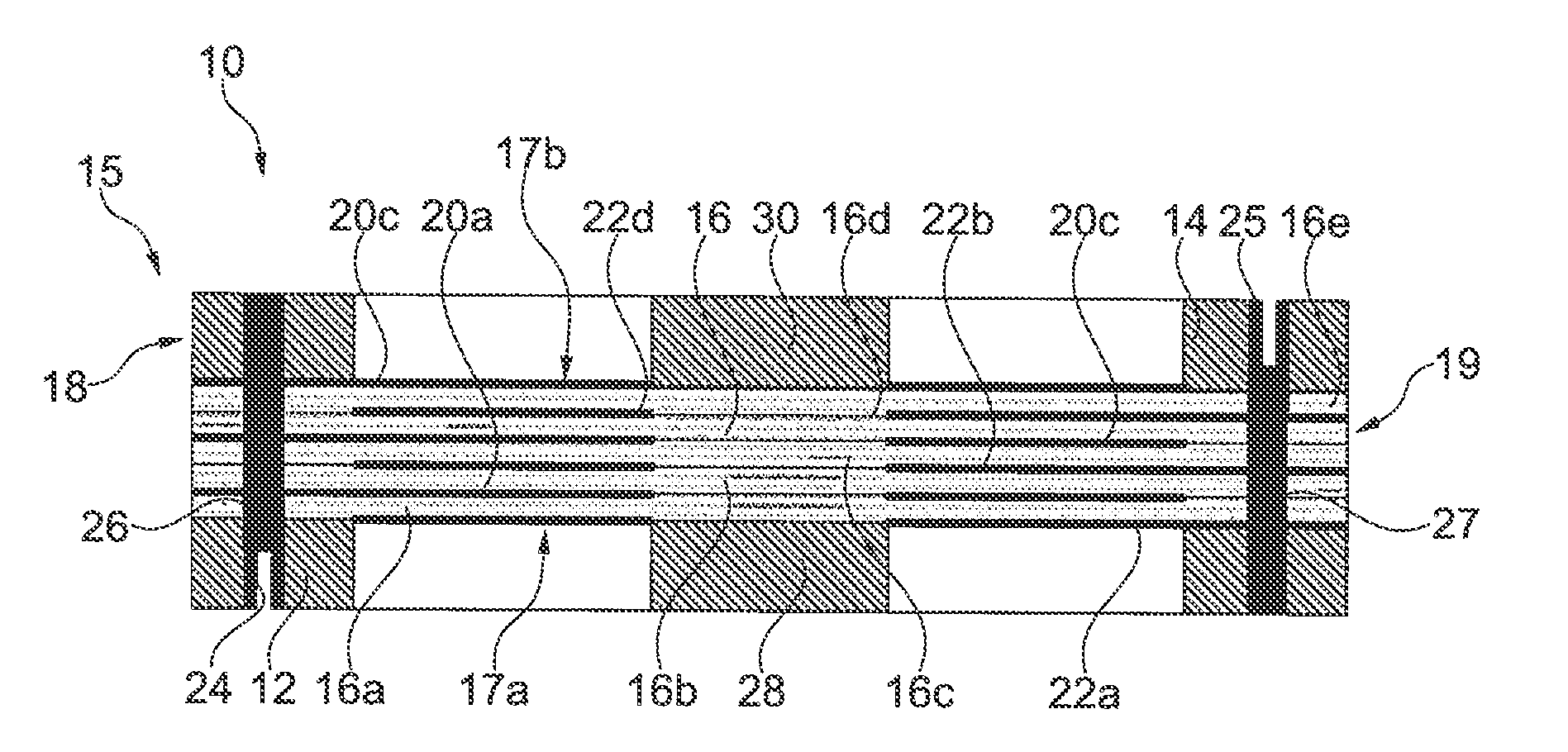
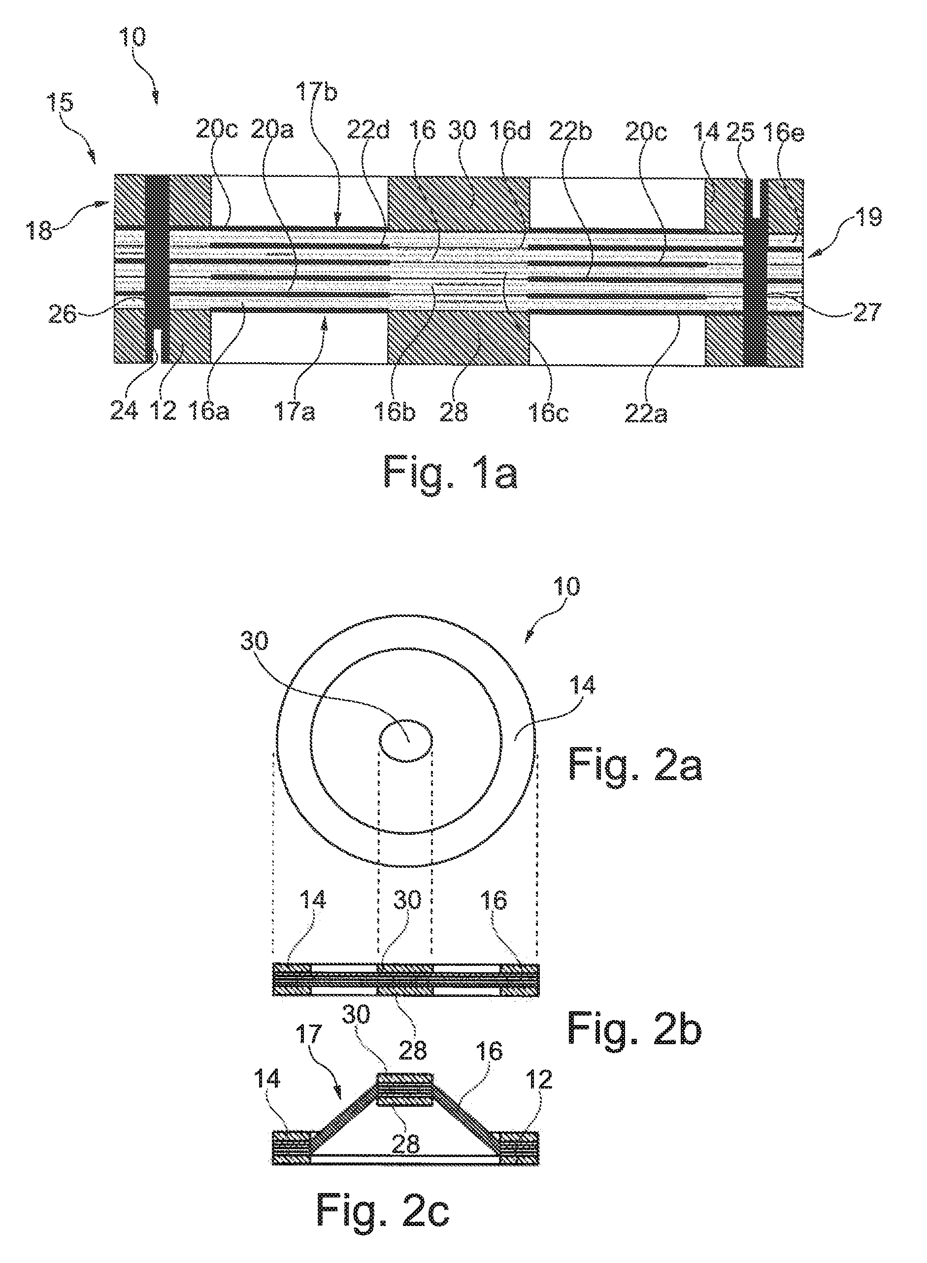
[0146]FIGS. 3a to 3c also show an overview of the diaphragm actuator 10.
[0147]The second embodiment of the diaphragm actuator 10 differs from the first embodiment in that the frame parts 12, 14, the diaphragm layers 16 and the connecting parts 28, 30 are substantially rectangular (see FIG. 3a). Only the corners are rounded.
[0148]Otherwise the structure and mode of operation of the diaphragm actuator 10 are the same. The advantage of the second embodiment is that a plurality of actuators can be disposed closely next to one another without space going to waste between them.
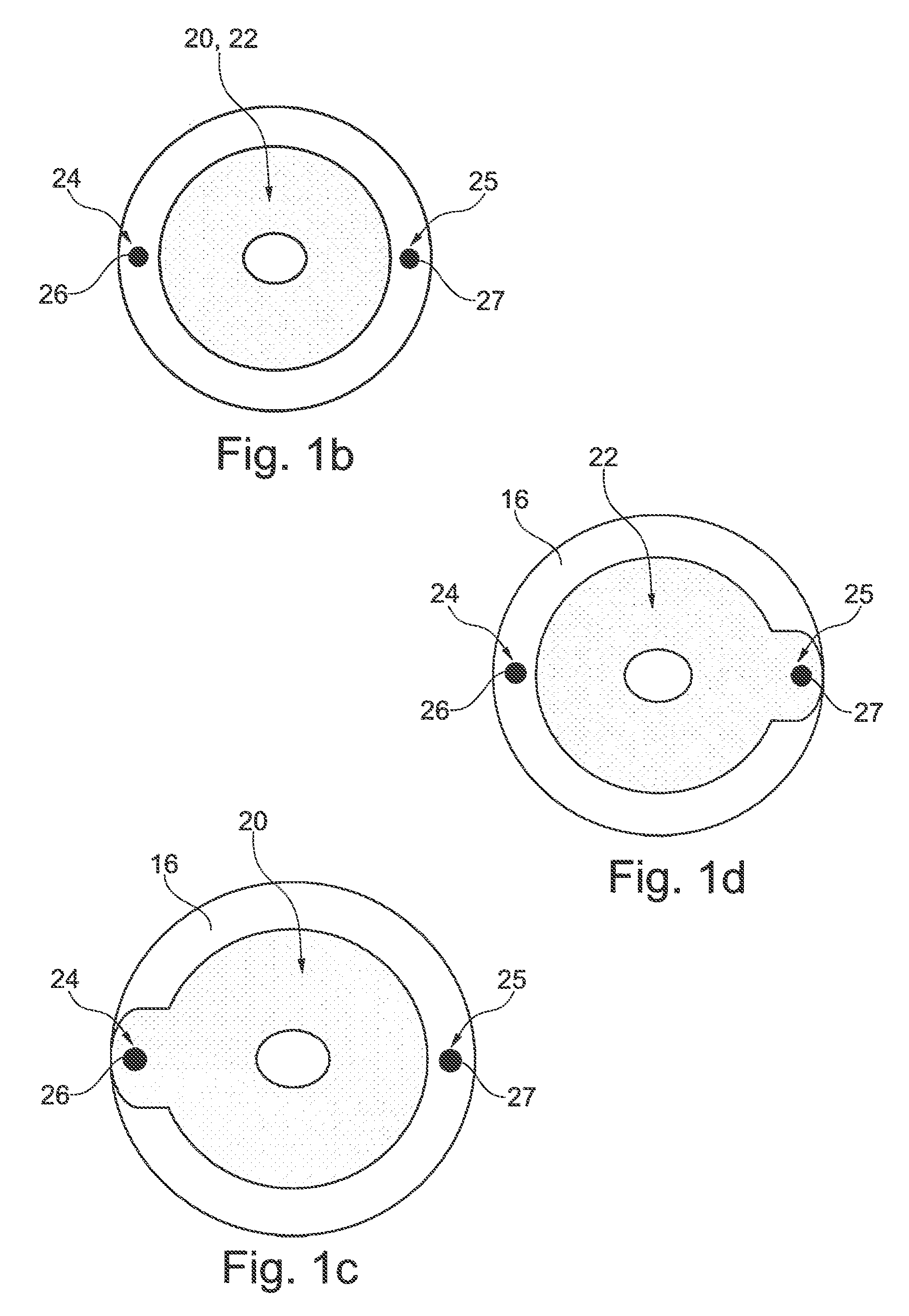
[0149]In FIGS. 3d to 3f the diaphragm actuator 10 of FIG. 3 is shown in a plan view (FIG. 3d) and two transverse cross-sectional views (FIGS. 3e and 3f) in different planes in order to clarify the formation of the two electrodes 20, 22 in accordance with the second embodiment.
[0150]FIGS. 3d to 3f are to be understood analogously to FIGS. 1b to 1d and so the expansion of the respective electrode 20, 22 is clear in pa...
third embodiment
[0153]As shown by the overview of FIG. 4, activation of the diaphragm actuator 10 in accordance with the third embodiment causes the individual diaphragm layers 16 to contract such that the diameter of the openings 32 is reduced.
[0154]In the illustrated embodiment, the openings 32 can contract so far that they close (see FIG. 4c) as compared with an initial condition (see FIGS. 4a and 4b). In this way, e.g. a flow cross-section can be directly controlled without the movement of the actuator having to be transferred to a valve element.
[0155]FIG. 5 illustrates a fourth embodiment of the diaphragm actuator 10 which substantially corresponds to the third embodiment, wherein the frame parts 12, 14, the diaphragm layers 16 and the openings 32 are not circular but rather substantially rectangular.
[0156]However, the remainder of the structure and the mode of operation of the diaphragm actuator 10 do not differ from the third embodiment; the openings 32 can also in this case be dosed (see FI...
ninth embodiment
[0164]FIG. 8 shows an overview of the diaphragm actuator 10, wherein the plan view (FIG. 8a) and the lower cross-sectional view (FIG. 8c) now show the electrically excited position of the diaphragm actuator 10.
[0165]In contrast to the previous embodiments, the frame parts 12, 14 of the diaphragm actuator 10 are flexible. For this purpose, the diaphragm actuators 10 and in particular the frame parts 12, 12 can be formed from a DEMES structure.
[0166]As shown by the overview in FIG. 8, the individual diaphragm layers 16 and therefore the stack 17 contract upon application of a voltage.
[0167]In this way the diaphragm actuator 10 and in particular the frame 15 thereof are transferred from an equilibrium condition which is favourable in terms of energy (FIG. 8b) to an excited condition (FIG. 8c).
[0168]In this way in the illustrated embodiment, the height of the diaphragm actuator 10 is reduced as shown in particular by a comparison with FIGS. 8b and 8c.
[0169]The frame parts 12, 14 and th...
PUM
 Abstract
Description
Claims
Application Information