Clog resistant fluid pathway

a fluid pathway and resistance technology, applied in the field of fluid manifolds, can solve the problems of limiting the useful life of the fluid manifold and unwanted dispersion, and achieve the effect of reducing back pressure turbulence and fluid friction

Inactive Publication Date: 2014-05-22
IDEX HEALTH & SCI
View PDF4 Cites 0 Cited by
  • Summary
  • Abstract
  • Description
  • Claims
  • Application Information

AI Technical Summary

Benefits of technology

[0006]The present invention provides a technical solution to the problems caused by sharp turn and sharp corner transition fluid passageways in fluid pathways in a fluidic manifold. The present invention provides a clog resistant leak tight smooth transition fluid path d

Problems solved by technology

The accumulation of such particulate form blockages or obstructions in the fluidic passageway and are difficult to clear and in many instances are not field serviceable by snaking a fish line or other wire product through the sharp turn or

Method used


Image

  • Clog resistant fluid pathway
  • Clog resistant fluid pathway
  • Clog resistant fluid pathway

Examples


Embodiment Construction

OF THE INVENTION

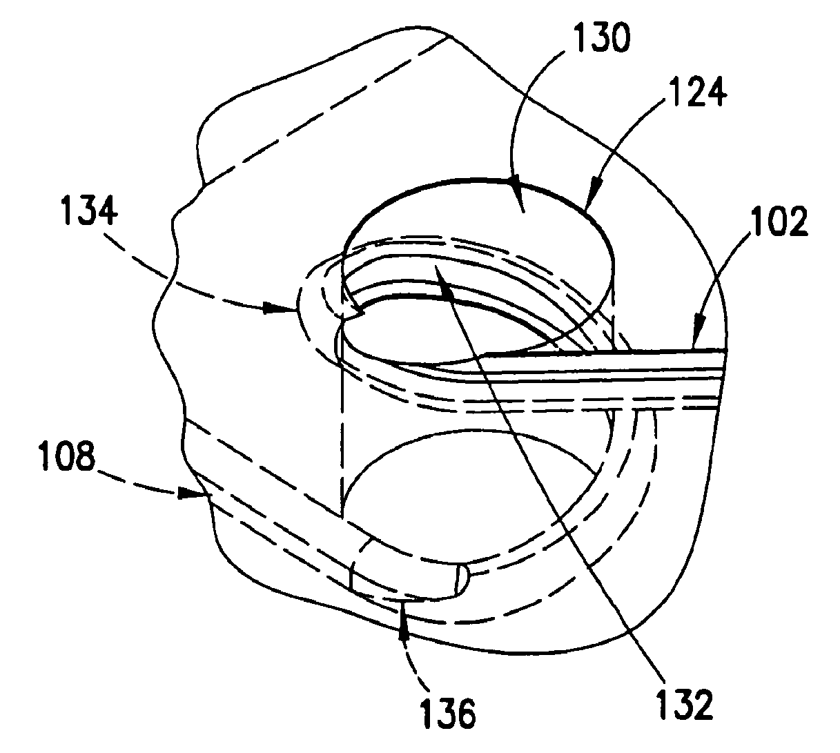
[0091]With reference to FIG. 2A a schematic diagram of a fluidic manifold having a smooth fluid transition passageway to provide a smooth clog resistant leak tight transition fluid passageway between fluid passageways on oppositely disposed major face surfaces in a layer in the fluidic manifold is shown in an example of the invention and is generally designated 100. In one example, the invention contemplates the diameter of a fluid passageway to be typically in the range of about 0.020 inches to 0.375 inches although not limited thereto and may be in the microfluidic diameter range. The fluidic manifold may be a single layer or multilayer fluidic manifold and of a material such as for example, a polymer plastic, aluminum or any other material suitable to carry out the function of the manifold. In this example, a groove or track 102 is machined or milled in the upwardly facing major face surface 104 of the layer 106 and a groove or track 108 is machined or milled in t...


PUM

PropertyMeasurementUnit
Angleaaaaaaaaaa
Sizeaaaaaaaaaa
Widthaaaaaaaaaa

Abstract

A clog resistant leak tight smooth transition fluid path directional turn in a fluid pathway that minimizes back pressure turbulence and fluid friction and is configured to be snakeable with a fish line or other wire product to clear or remove potential blockages due to particulate carried by fluid flowing in the fluid pathway is presented. In one example the transition fluid path is an insert having a predefined size and shape configured to be received in a complementary sized and shaped opening in the layer of a fluidic manifold. A leak tight communication passageway is defined by a groove following a smooth curved path located between a surface of the insert in facing relationship with a matching surface of the opening in the layer between the entry fluid path and the exit fluid path.

Description

FIELD OF THE INVENTION[0001]The present invention relates generally to fluidic manifolds and deals more particularly with fluidic passageways in such fluidic manifolds and more specifically with clog resistant leak tight smooth turn fluid pathway transitions in such fluidic passageways. The present invention also more specifically deals with fluid pathway transitions in such fluidic passageways in fluidic manifolds that are serviceable or snakeable with a fishline or other wire product to clear out potential obstructions or clogs.BACKGROUND OF THE INVENTION[0002]Fluidic manifolds are in common use in technologies requiring control of the flow of fluids in fields such as medical equipment, analytical equipment, industrial and research equipment and the like. A fluidic manifold may be defined as having one or more inlet and outlet ports that are internally connected in a maze of passageways, channels, and cavities to conduct the flow of fluids. A fluidic manifold may be populated with...

Claims


Application Information

Patent Timeline
IPC IPC(8): F16L3/00
CPCB01L3/502746B01L2200/0636B01L2300/0816B01L2300/0861B01L2300/0874B01L2400/084F15D1/04B01J4/001B01J2219/00011B01J2219/00247B01J2219/00256B01J2219/247Y10T29/49826F16L3/00
Inventor DICKINSON, JAMES L.
Owner IDEX HEALTH & SCI
Why Eureka
Try Eureka