
Drop port based shared risk link group systems and methods

a technology of shared risk and drop port, applied in the field of optical networking systems and methods, can solve the problems of multiple different services suffering from a common network failure, single point of failure, and overlapping networks occupying the same space more common in fiber constrained networks

Active Publication Date: 2014-05-29
CIENA
View PDF7 Cites 16 Cited by
  • Summary
  • Abstract
  • Description
  • Claims
  • Application Information

AI Technical Summary

Benefits of technology

The patent describes a method and network for ensuring absolute route diversity between two networks. This is achieved by assigning links in one network to another network, and providing details of these links to a control plane in the other network. The control plane calculates paths for connections between network elements in the other network using the shared risk link group information and the details of the links in the first network. This guarantees that no single path can be used for the connections, ensuring that the network is always resilient to failure. The technical effect of this invention is to improve the reliability and resilience of network connections, ensuring that they can withstand failure without disrupting the overall network.

Problems solved by technology

In fiber constrained networks, network types (access, metro, regional, and / or core networks) may overlap to a point when one network's line port may be another network's drop port resulting in single points of failure.
However, overlapping networks occupying the same are more common in fiber constrained networks and a single points of failure in the network because of incomplete understanding of the common SRLG in the networks.
Generally, an SRLG is a concept that multiple different services may suffer from a common network failure if they are sharing a common failure risk such as, without limitation, a common fiber, a fiber conduit, common hardware, etc.
Conventionally, there is no way to identify SRLG information between networks resulting in unpredictable failure modes, unidentified shared risks on connections spanning different networks, and the like.

Method used


Image

  • Drop port based shared risk link group systems and methods
  • Drop port based shared risk link group systems and methods
  • Drop port based shared risk link group systems and methods

Examples


Embodiment Construction

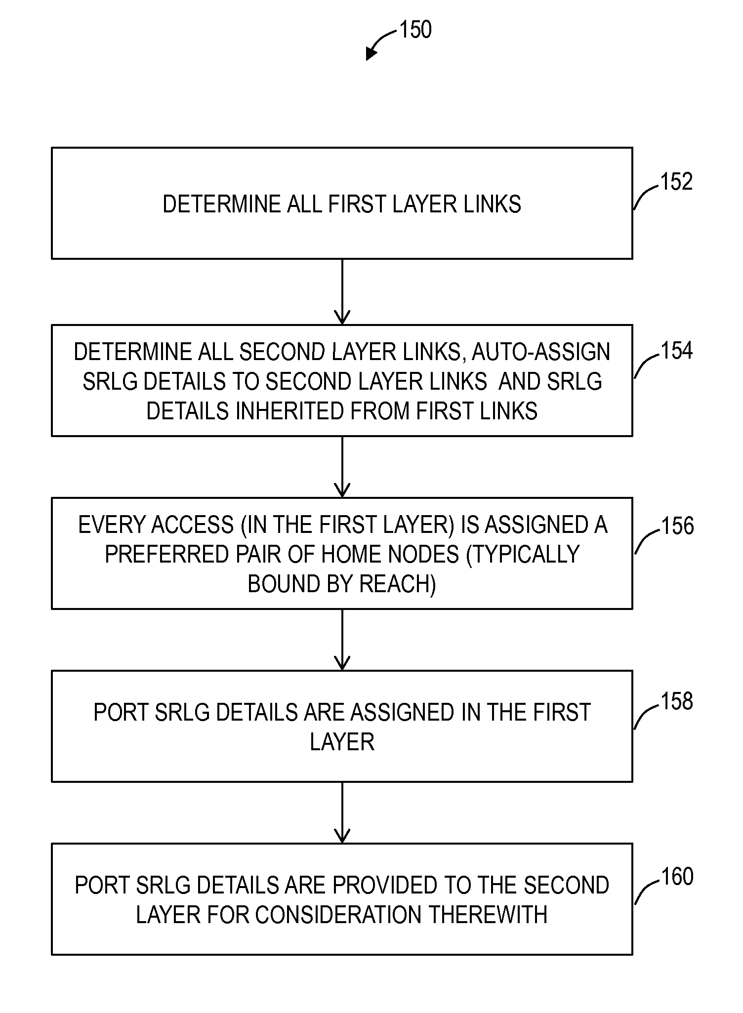
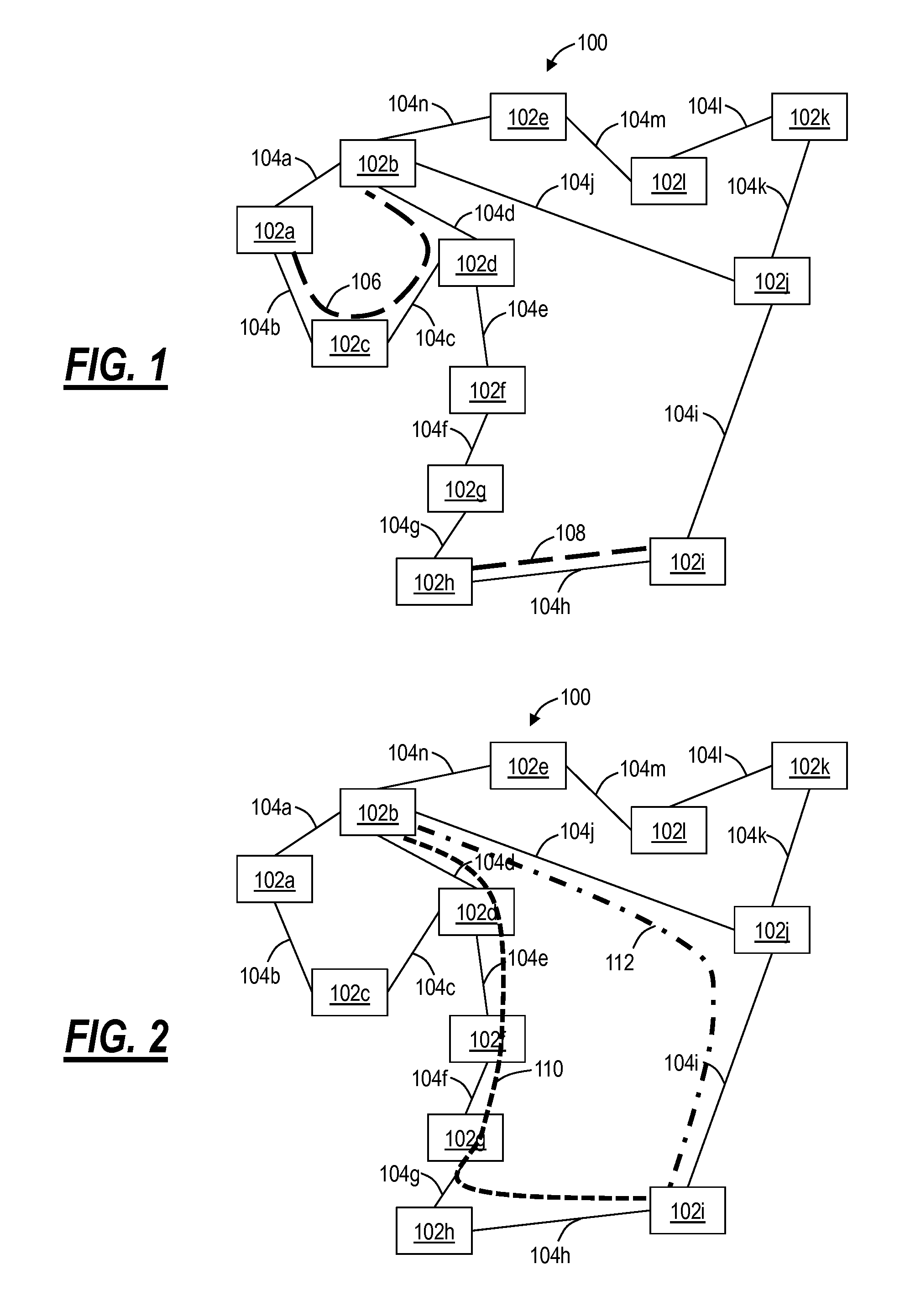
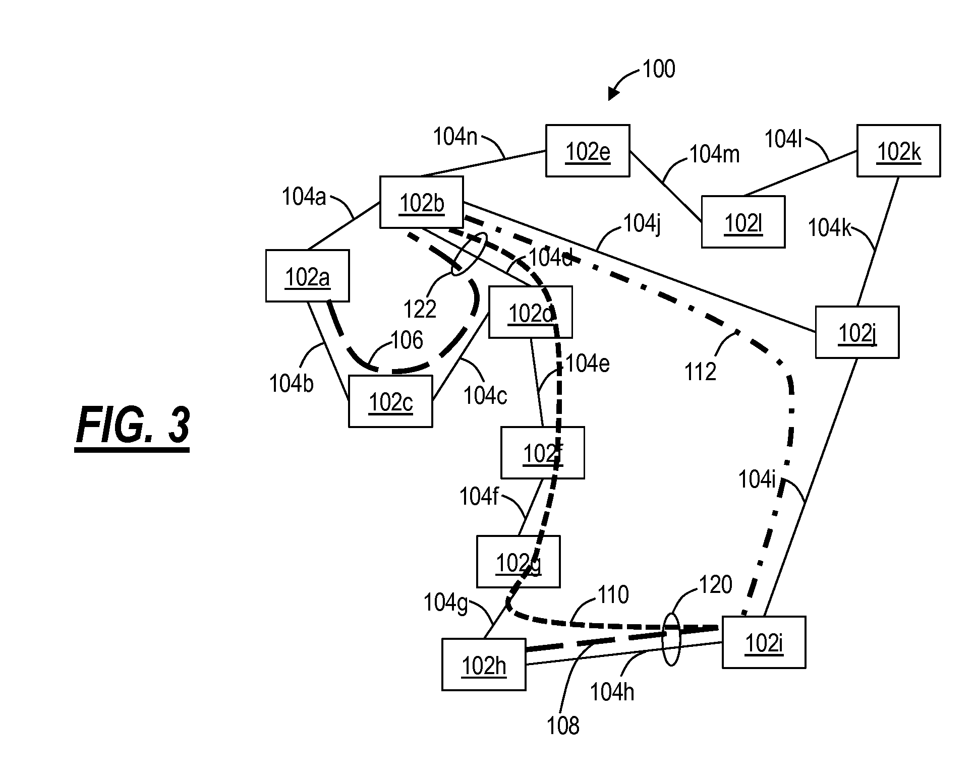
[0023]In various exemplary embodiments, drop port based shared risk link group (SRLG) systems and methods assign SRLG information to drop ports. Thus, drop side SRLG information can be shared between different networks enabling a combination with line side SRLG information within a network to identify and prevent single points of failure across the networks. Typically, SRLG details are assigned to line ports (NNI ports) within a network and this information is not shared with external networks for routing a connection through the network and the external networks. By assigning SRLG details to a drop port, this information can be relayed between the network and the external networks and considered when planning a route through all of the networks.

[0024]Referring to FIGS. 1-3, in an exemplary embodiment, network diagrams illustrate a network 100 of various interconnected nodes 102a-102l. The nodes 102a-102l are physical locations such as, without limitation, central offices (COs), poi...


PUM


Abstract

Drop port based shared risk link group (SRLG) systems and methods assign SRLG information to drop ports in another level or layer of a network. Thus, drop side SRLG information can be shared between different networks or layers enabling a combination with line side SRLG information within a network to identify and prevent single points of failure across the networks. Typically, SRLG details are assigned to line ports (NNI ports) within a network and this information is not shared with external networks or network layers for routing a connection through the network and the external networks. By assigning SRLG details to a drop port, this information can be relayed between the network and the external networks and considered when planning a route through all of the networks.

Description

FIELD OF THE INVENTION[0001]Generally, the field of art of the present disclosure pertains to optical networking systems and methods, and more particularly, to drop port based shared risk link group (SRLG) systems and methods providing mechanisms to share SRLG details between different networks or network layers.BACKGROUND OF THE INVENTION[0002]Optical networks and the like (e.g., wavelength division multiplexing (WDM), Synchronous Optical Network (SONET), Synchronous Digital Hierarchy (SDH), Optical Transport Network (OTN), Ethernet, and the like) at various layers are deploying control plane systems and methods. Control plane systems and methods provide automatic allocation of network resources in an end-to-end manner. Exemplary control planes may include Automatically Switched Optical Network (ASON) as defined in G.8080 / Y.1304, Architecture for the automatically switched optical network (ASON) (02 / 2005), the contents of which are herein incorporated by reference; Generalized Mult...

Claims


Application Information

Patent Timeline
Patent Type & Authority Applications(United States)
IPC IPC(8): H04B10/07H04L45/24
CPCH04B10/07H04J14/0273H04J14/029H04L45/24H04J14/0286H04L45/64H04J14/0256H04L41/0896
Inventor SWINKELS, GERARD LEOYEUNG, DAVID MAN-WAH
Owner CIENA
Learn More