Image processing apparatus and control method for image processing apparatus
a technology of image processing apparatus and control method, which is applied in the direction of electrographic process, instruments, transportation and packaging, etc., can solve the problems of reducing user convenience, and achieve the effect of reducing unnecessary power consumption, preventing unnecessary returns, and improving user convenien
- Summary
- Abstract
- Description
- Claims
- Application Information
AI Technical Summary
Benefits of technology
Problems solved by technology
Method used
Image

Examples
first embodiment
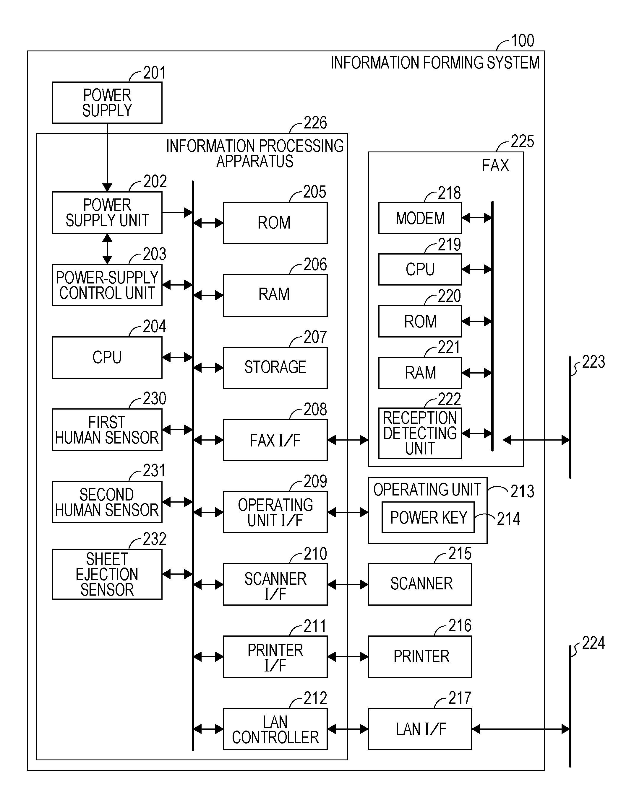
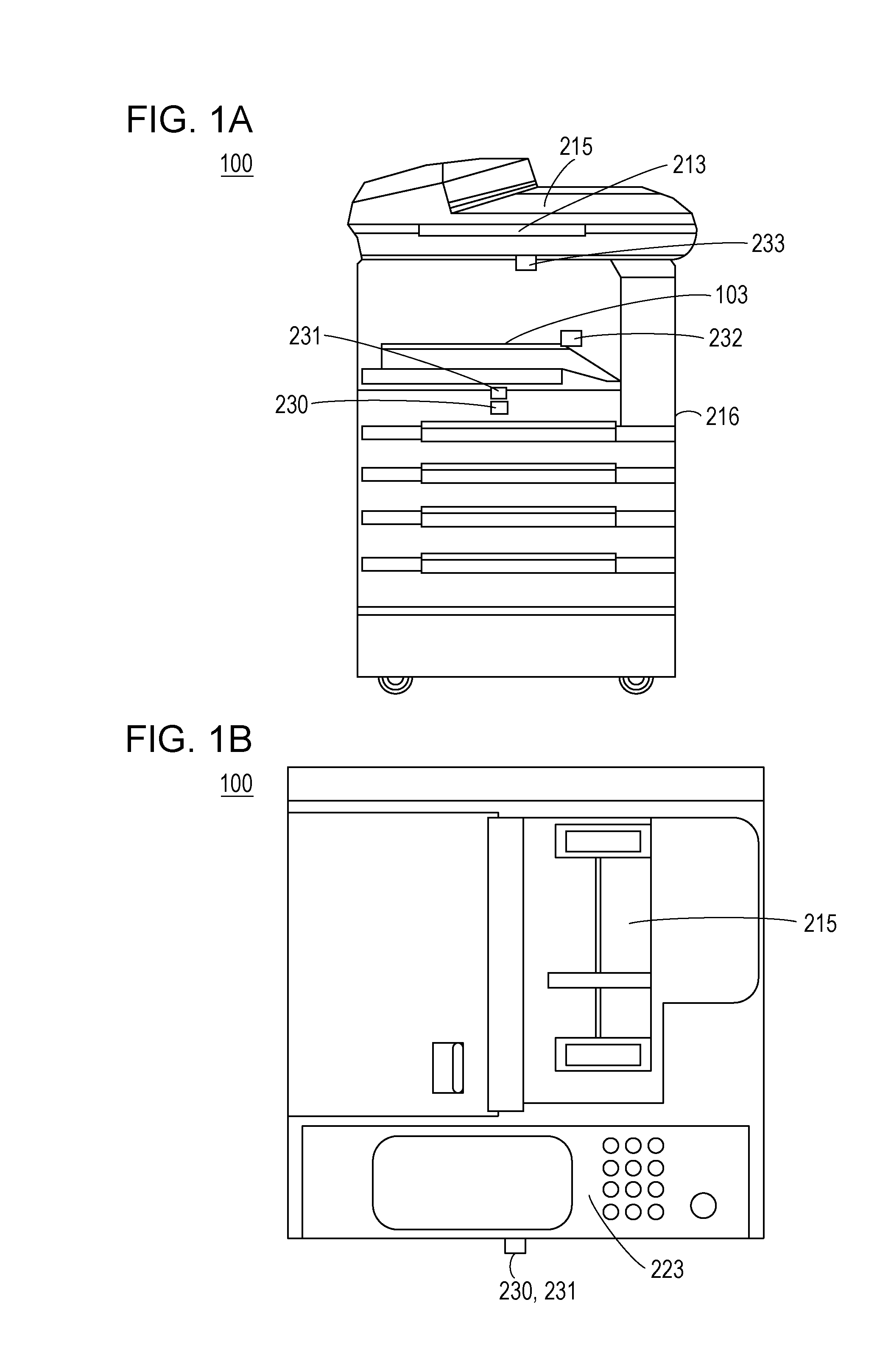
[0027]FIGS. 1A and 1B illustrate appearances of an image processing apparatus according to an embodiment of the present invention. FIG. 1A corresponds to a front view of the image processing apparatus. FIG. 1B corresponds to a top view of the image processing apparatus.
[0028]As illustrated in FIGS. 1A and 1B, an image processing apparatus 100 includes an operating unit 213, a scanner 215, an internal finisher (internal sheet ejecting unit) 103, and a printer 216. The image processing apparatus 100 has copy, print, facsimile, scan and other functions.
[0029]The image processing apparatus 100 is capable of operating in one of a normal power mode (first power state), a power-saving mode 2 (second power state) which consumes less power than the normal power mode, and a power-saving mode 1 (third power state) which consumes less power than the power-saving mode 2.
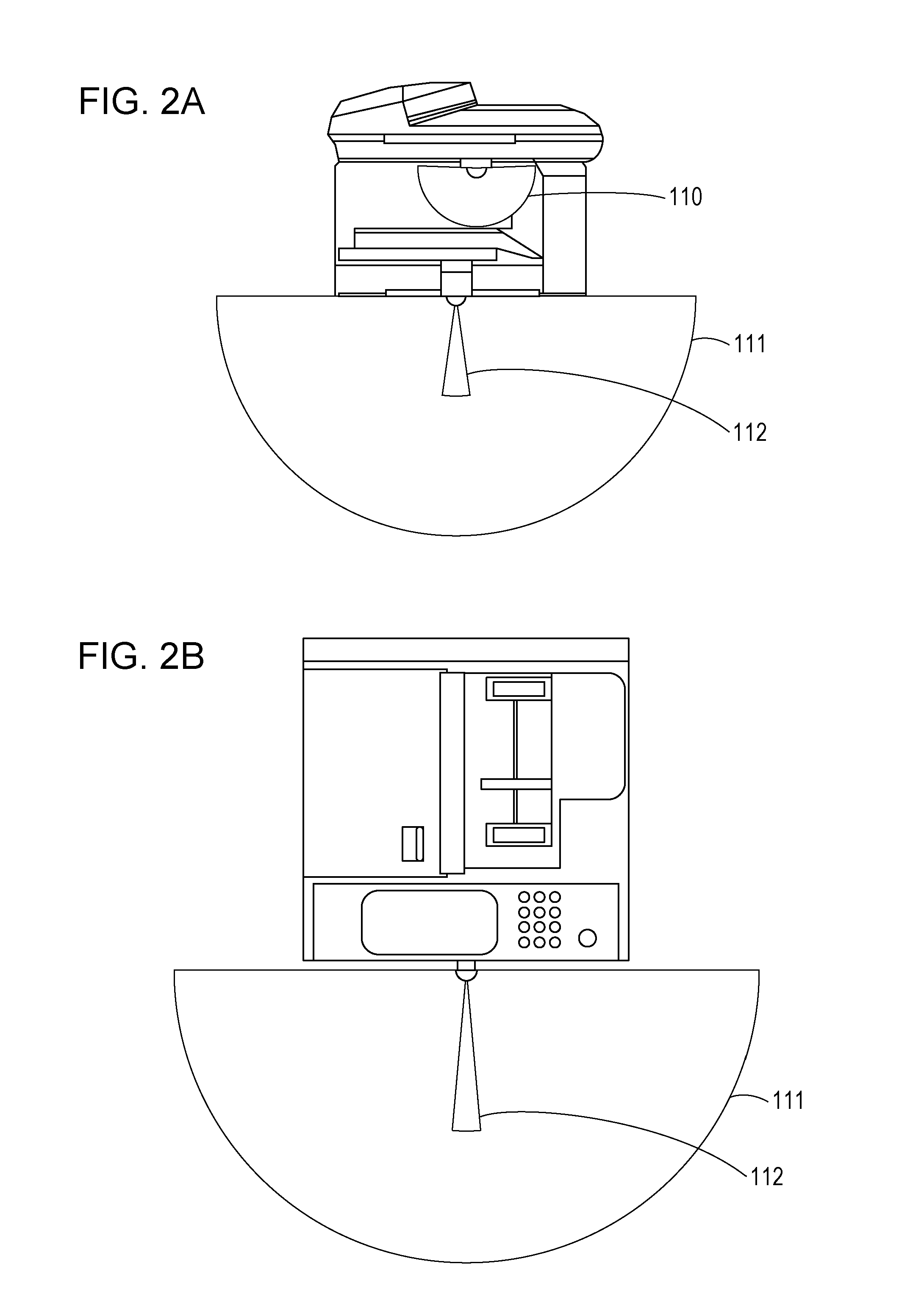
[0030]The image processing apparatus 100 further includes a first human sensor 230 and a second human sensor 231. The first hum...
second embodiment
[0095]A second embodiment will be described below with focus on differences from the first embodiment. According to the first embodiment, two human sensors and a sheet ejection sensor are used to control over output of a return instruction to a normal power mode from the first sheet ejection sensor 232 (or second human sensor 231) in order to prevent a unnecessary return from a power-saving mode. According to a second embodiment, instead of control over output of a return instruction, feeding to the second human sensor 231 is delayed for prevention of an unnecessary return from a power-saving mode. Differences from the first embodiment will be described.
[0096]FIG. 7A is a block diagram illustrating an example of a power feeding configuration of an image processing apparatus 100 according to the second embodiment. Like numbers refer to like parts throughout. An SW 420 is a switch usable for turning on and off feeding to the second human sensor 231. If the SW 311 has an OFF state, the...
third embodiment
[0127]A third embodiment will be described below with focus on differences from the first embodiment. According to the first embodiment, two human sensors and a sheet ejection sensor are used to control over output of a return instruction to a normal power mode from the first sheet ejection sensor 232 (or second human sensor 231) in order to prevent a unnecessary return from a power-saving mode. According to the third embodiment, instead of control over output of a return instruction, two sheet ejection sensors are used to restrict an unnecessary return from a power-saving mode in accordance with a detection state of the second sheet ejection sensor 233 while a return is being delayed in accordance with a detection state of the first sheet ejection sensor 232. This configuration allows precise identification of a purpose of a human approaching the image processing apparatus 100 for more convenience. Differences from the first embodiment will be described.
[0128]FIGS. 10A to 10C are b...
PUM
 Abstract
Description
Claims
Application Information
 - R&D
- Intellectual Property
- Life Sciences
- Materials
- Tech Scout
- Unparalleled Data Quality
- Higher Quality Content
- 60% Fewer Hallucinations
Browse by: Latest US Patents, China's latest patents, Technical Efficacy Thesaurus, Application Domain, Technology Topic, Popular Technical Reports.
© 2025 PatSnap. All rights reserved.Legal|Privacy policy|Modern Slavery Act Transparency Statement|Sitemap|About US| Contact US: help@patsnap.com